  |
|
|
|
|
|
|
  |
|
|
|
|
|
|

What
do you think?
|

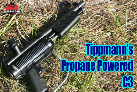
Tippmann C3 By Bill Mills - Photos by Dawn Mills - Dec 2005 Overview - How It Works - Disassembly - Testing - Raw Test Data
How It Works Understanding how the C3 works all comes down to the loading and firing sequence.
Gas grills commonly use piezoelectric spark generators as their ignition source. While the C3’s electronic ignition may be more complex, and require a battery, it has a number of advantages. Immediately noticeable to the player is the short microswitch defined trigger pull. The C3 design team cites their main reason for going electronic was reliability, and this is two fold. The electronic ignition has only one moving part, which does not see much stress – the microswitch. This reduces the chance of a mechanical failure. The electronic circuit can also fire more than one spark with each trigger pull. If the first spark doesn’t manage to ignite the fuel/air mixture, the one after it, or the one after that will. This ensures on field reliability.
As the fuel/air mixture combusts, the expanding pressure front of hot exhaust gasses can’t go out through the holes in the main piston – they are blocked, and it can’t escape via the air intake holes either, as they are blocked by the rubber ring. The remaining place for gas pressure to escape from the combustion chamber is by pressing back on a spring-operated piston at the rear of the gun. This rear piston controls the velocity, and Tippmann simply calls it the piston.
When the combustion gasses push the piston back, they open up a pathway through which they can flow upward through a passage into the back of the barrel. From there they enter the bolt, and further expand propelling the paintball out of the barrel. The piston is key to the C3’s operation. When the velocity adjustment screw is turned inward, it puts more spring pressure on the piston. This in turn means that the piston pushes harder against the exhaust gasses, and doesn’t open as far. It takes longer for the exhaust gasses to flow through the tighter space, resulting in a lower velocity shot. When the velocity adjuster screw is backed out, there is less pressure, the piston opens further, and higher velocities are achieved. Four staggered holes on each side of the receiver act as a safety relief. If the pressure on the piston from its spring were too weak to limit the velocity properly, piston would push back further, and gas would be vented out of these holes. This acts as a safety limiter preventing the C3 from being cranked up to excessive velocities. Because the velocity is adjusted by
limiting flow of exhaust gasses after combustion, velocity setting has
no effect on the amount of gas used to fire each shot – efficiency remains
the same at 220 fps as it does at 280 fps.
Continue to Disassembly |
| Copyright © 1992-2019
Corinthian Media Services. WARPIG's webmasters can be reached through our feedback form. All articles and images are copyrighted and may not be redistributed without the written permission of their original creators and Corinthian Media Services. The WARPIG paintball page is a collection of information and pointers to sources from around the internet and other locations. As such, Corinthian Media Services makes no claims to the trustworthiness or reliability of said information. The information contained in, and referenced by WARPIG, should not be used as a substitute for safety information from trained professionals in the paintball industry. |