Tippmann C3
By Bill Mills - Photos
by Dawn Mills - Dec 2005
Overview
- How It Works - Disassembly
- Testing - Raw Test
Data
Disassembly
 Caution:
This guide is meant to provide augment the reader's knowledge and should
not be considered a substitute for the manufacturer's literature and advice. Caution:
This guide is meant to provide augment the reader's knowledge and should
not be considered a substitute for the manufacturer's literature and advice.
While a pump paintgun is usually simpler
in construction than a semi, the C3 is rather complex in design.
Fortunately, the typical user will need to do little more than adjust the
velocity, clean the barrel, and change the battery. As always, maintenance
work should only be performed after the paintgun has been unloaded of both
paintballs and its propellant supply, and dry-fired multiple times in a
safe direction to ensure that no propellant gasses are still in the system.
Cleaning the barrel is easy, especially
with the Straight Shot Squeegee. For a more thorough cleaning, especially
of the bolt or the ball detent, the barrel needs to be removed.
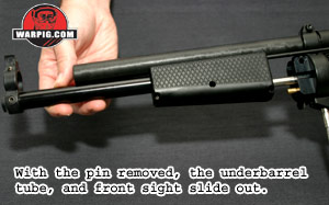
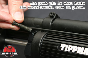 The
front sight and the under-barrel tube are held in place by a push-pin,
that slides into the front valve body and through a hole in the back of
the under-barrel tube. Popping this pin out by hand releases the
under-barrel tube so it can be slid forward and out. The
front sight and the under-barrel tube are held in place by a push-pin,
that slides into the front valve body and through a hole in the back of
the under-barrel tube. Popping this pin out by hand releases the
under-barrel tube so it can be slid forward and out.
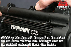 With
the under-barrel tube out of the way the front end of the linkage arm (the
rod connecting the pump to the bolt) can be pushed inward to the space
previously blocked by the under-barrel tube, and be freed from its locked
position in the left side of the pump. With
the under-barrel tube out of the way the front end of the linkage arm (the
rod connecting the pump to the bolt) can be pushed inward to the space
previously blocked by the under-barrel tube, and be freed from its locked
position in the left side of the pump.
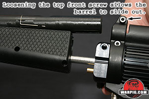
The top-forward most receiver bolt clamps
the receiver tightly onto the C3s un-threaded barrel, much like the barrel
retention system of a Palmers Blazer. After loosening this bolt,
the barrel is able to slide within the receiver. It must be moved
forward a fraction of an inch so that the linkage arm is clear of the receiver.
The linkage arm can be lifted out of the bolt and set aside.
 At
this point the barrel can slide out of the receiver, through it will probably
need some wiggling to do so, as the barrel seal o-ring will be pressing
against it. With the barrel out, both it and the bolt can be inspected
and cleaned. The ball detent can also be inspected and repaired by
bending, or replaced if necessary. It should be noted that once the
barrel is removed by this method, it is often difficult to reinstall it
by simply sliding it back in, as this will many times cause the barrel
seal o-ring to be pushed out of place and to bind between the barrel and
receiver halves. Reinstalling the barrel will usually mean taking
the two receiver halves apart, and then closing them back up around the
barrel. At
this point the barrel can slide out of the receiver, through it will probably
need some wiggling to do so, as the barrel seal o-ring will be pressing
against it. With the barrel out, both it and the bolt can be inspected
and cleaned. The ball detent can also be inspected and repaired by
bending, or replaced if necessary. It should be noted that once the
barrel is removed by this method, it is often difficult to reinstall it
by simply sliding it back in, as this will many times cause the barrel
seal o-ring to be pushed out of place and to bind between the barrel and
receiver halves. Reinstalling the barrel will usually mean taking
the two receiver halves apart, and then closing them back up around the
barrel.
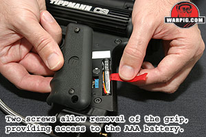 Before
going further into disassembly, it is important to remove the left side
grip panel, and take out the AAA battery hidden beneath it. Not only
will this allow the battery to be tested and inspected for corrosion, but
it also stands as protection from accidentally triggering the ignition
circuit and getting a 40,000-volt shock from exposed components. Before
going further into disassembly, it is important to remove the left side
grip panel, and take out the AAA battery hidden beneath it. Not only
will this allow the battery to be tested and inspected for corrosion, but
it also stands as protection from accidentally triggering the ignition
circuit and getting a 40,000-volt shock from exposed components.
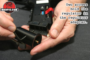 Further
disassembly requires removing the propane regulator from its position at
the bottom of the grip frame. Two screws pass through the regulator
and into its mount. With these removed, the regulator is free from
the grip, but still connected to the marker by its steel braided hose. Further
disassembly requires removing the propane regulator from its position at
the bottom of the grip frame. Two screws pass through the regulator
and into its mount. With these removed, the regulator is free from
the grip, but still connected to the marker by its steel braided hose.
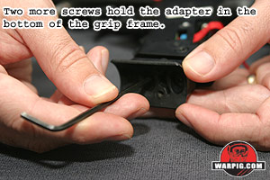 Two
more screws go through the regulator adapter a cradle shaped mount
and into a pair of square nuts in the bottom of the grip frame. These
are easily removed with a hex wrench, allowing the mount adapter to be
set aside until it is needed for reassembly. Two
more screws go through the regulator adapter a cradle shaped mount
and into a pair of square nuts in the bottom of the grip frame. These
are easily removed with a hex wrench, allowing the mount adapter to be
set aside until it is needed for reassembly.
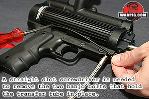 On
the right hand side of the C3, the fuel transfer tube will then need to
be removed. This is a thin piece of hose, similar in size and flexibility
to that used in Autococker pneumatics. It is through this tube that
propane flows from the fuel injector around the main combustion chamber,
to be introduced to the back end of the chamber. Both ends of the
transfer tube are secured by banjo bolt style fittings. A banjo-bolt
is a hollow screw that allows the gas to flow through it. A socket
wrench or straight slot screwdriver is needed to remove these fittings.
On each fitting is an o-ring to provide a secure seal, these should be
inspected and cleaned if dirty, as should the surfaces to which they mate. On
the right hand side of the C3, the fuel transfer tube will then need to
be removed. This is a thin piece of hose, similar in size and flexibility
to that used in Autococker pneumatics. It is through this tube that
propane flows from the fuel injector around the main combustion chamber,
to be introduced to the back end of the chamber. Both ends of the
transfer tube are secured by banjo bolt style fittings. A banjo-bolt
is a hollow screw that allows the gas to flow through it. A socket
wrench or straight slot screwdriver is needed to remove these fittings.
On each fitting is an o-ring to provide a secure seal, these should be
inspected and cleaned if dirty, as should the surfaces to which they mate.
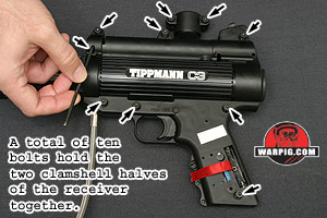 A
total of ten bolts hold the two receiver halves together, eight on the
main body of the receiver, and two at the top of the feedneck. In
a move that makes life easier for C3 owners, Tippmanns design crew made
all of these bolts the same length, so there is no need to worry about
keeping them in order for reassembly. All ten of these bolts screw
into nuts sitting in hexagonal recesses in the right half of the receiver.
By screwing into hardened steel nuts, rather than the softer polymer of
the receiver, the C3 is well protected from thread stripping problems. A
total of ten bolts hold the two receiver halves together, eight on the
main body of the receiver, and two at the top of the feedneck. In
a move that makes life easier for C3 owners, Tippmanns design crew made
all of these bolts the same length, so there is no need to worry about
keeping them in order for reassembly. All ten of these bolts screw
into nuts sitting in hexagonal recesses in the right half of the receiver.
By screwing into hardened steel nuts, rather than the softer polymer of
the receiver, the C3 is well protected from thread stripping problems.
In the C3 tested for review, all of
the receiver nuts were firmly seated in their slots. A user who finds
any which are loose may wish to secure them in their place with a tiny
drop of cyanoacrylate super-glue on one of their outside edges (being very
careful not to get any on their threaded inner surfaces.) This will
help prevent them from dropping out accidentally and hiding under a chair
leg during disassembly, but still allow them to be removed with mild effort
(simply screwing a bolt into them from the right side and wiggling and
pulling) if needed.
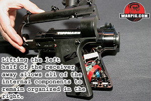 With
all ten of the receivers bolts either removed, or at lease loosened out
of contact with their nuts, the left half of the receiver can be lifted
away from the right. While one could take every thing apart, keeping
the right side down, and lifting off the left will keep all of the parts
organized and sitting in the right receiver half. The small parts
to watch out for at this point are the square nuts in the bottom of the
grip, the trigger spring, the trigger, and the two steel pins that hold
the trigger in place. All of these parts should sit nicely in the
right half of the receiver, but some may attempt a getaway at this point,
especially the trigger spring. Much like the receiver nuts, the two
bottom-line nuts can be secured into the right receiver half with a tiny
dot of super glue, making them easier to manage. With
all ten of the receivers bolts either removed, or at lease loosened out
of contact with their nuts, the left half of the receiver can be lifted
away from the right. While one could take every thing apart, keeping
the right side down, and lifting off the left will keep all of the parts
organized and sitting in the right receiver half. The small parts
to watch out for at this point are the square nuts in the bottom of the
grip, the trigger spring, the trigger, and the two steel pins that hold
the trigger in place. All of these parts should sit nicely in the
right half of the receiver, but some may attempt a getaway at this point,
especially the trigger spring. Much like the receiver nuts, the two
bottom-line nuts can be secured into the right receiver half with a tiny
dot of super glue, making them easier to manage.
At the very rear of the receiver is
a flexible plastic end cap, which is easily removed at this time.
The combustion chamber the aluminum tube that is the core of the C3,
still has a few things in the way of just lifting it out.
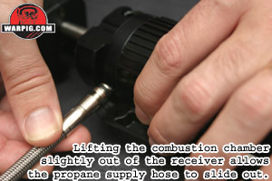 Lifting
up the front end of the chamber about a half inch allows the fitting on
the end of the braided gas line from the regulator to be pulled out of
the front valve body. The gas line is held in by ridges in the receiver,
rather than being threaded into the valve front. This means it can
be sealed with an o-ring rather than needing sealing tape or thread locking
compound, so disassembly and reassembly goes much faster. At the
end of the hose is another o-ring, which should be inspected for nicks
or damage. Lifting
up the front end of the chamber about a half inch allows the fitting on
the end of the braided gas line from the regulator to be pulled out of
the front valve body. The gas line is held in by ridges in the receiver,
rather than being threaded into the valve front. This means it can
be sealed with an o-ring rather than needing sealing tape or thread locking
compound, so disassembly and reassembly goes much faster. At the
end of the hose is another o-ring, which should be inspected for nicks
or damage.
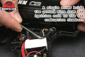 At
the back of the combustion chamber, on the bottom is a hex head screw holding
the grounding wire from the ignition coil. This line completes the
electrical circuit, allowing a spark to jump from the spark plug to the
closes un-insulated surface in the combustion chamber which is usually
one of the center rings on the exhaust piston valve. The ground wire,
and its lock washer are removed by unscrewing their screw. At
the back of the combustion chamber, on the bottom is a hex head screw holding
the grounding wire from the ignition coil. This line completes the
electrical circuit, allowing a spark to jump from the spark plug to the
closes un-insulated surface in the combustion chamber which is usually
one of the center rings on the exhaust piston valve. The ground wire,
and its lock washer are removed by unscrewing their screw.
 Once
unencumbered, the combustion chamber will easily lift out of the right
receiver half, with the pump and exhaust piston assembly still attached. Once
unencumbered, the combustion chamber will easily lift out of the right
receiver half, with the pump and exhaust piston assembly still attached.
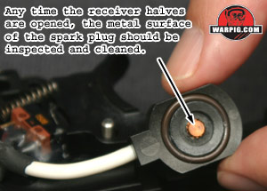
The spark plug, assembly, which simply
presses up against the bottom of the combustion chamber will fall away,
as it is wired to the ignition circuitry. Any time these two components
are apart, the metallic spark plug surface should be cleaned by wiping
it with a piece of cloth.
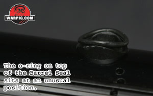 It
is important to note, when disassembling the C3 for the first time, how
the o-ring sits in the barrel seal. The barrel seal is a tube that
routes the exhaust gasses from the combustion chamber up to the barrel
where the bolt will direct them to the paintball. In a groove on
the barrel seals top is an o-ring that is bent into a saddle shape, sealing
the seal to the barrel. It is this o-ring shifting out of place that
can make sliding the barrel back in a difficult task. It
is important to note, when disassembling the C3 for the first time, how
the o-ring sits in the barrel seal. The barrel seal is a tube that
routes the exhaust gasses from the combustion chamber up to the barrel
where the bolt will direct them to the paintball. In a groove on
the barrel seals top is an o-ring that is bent into a saddle shape, sealing
the seal to the barrel. It is this o-ring shifting out of place that
can make sliding the barrel back in a difficult task.
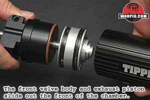 The
front valve body can be removed from the combustion chamber simply by twisting
it loose, and sliding it forward. Along with it will come the exhaust
piston from the center of the combustion chamber. The pistons seals
can then be checked for damage and lubrication. The
front valve body can be removed from the combustion chamber simply by twisting
it loose, and sliding it forward. Along with it will come the exhaust
piston from the center of the combustion chamber. The pistons seals
can then be checked for damage and lubrication.
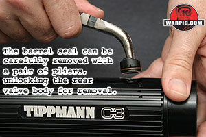 The
barrel seal also acts as a key, locking the rear valve body into the combustion
chamber. It is held in place by the friction of an o-ring around
its lower end. It is removed by carefully grasping one of its edges
with a pair of needle nosed pliers and wiggling it out. The
barrel seal also acts as a key, locking the rear valve body into the combustion
chamber. It is held in place by the friction of an o-ring around
its lower end. It is removed by carefully grasping one of its edges
with a pair of needle nosed pliers and wiggling it out.
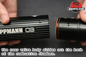
With the barrel seal out, the rear valve
body comes out of the back of the combustion chamber, leaving the chamber
as a simple piece of pipe. Care should be taken, when removing the
rear valve body, not to twist it very much, or its front o-ring is likely
to bunch up and stick out of the barrel seal opening in the combustion
chamber. If this happens, the o-ring must be carefully worked back
into place, or it may be sheared off when the rear valve body is pulled
further out.
 On
the front of the rear valve body is a flexible orange seal. This
seal rests up against 10 gas passages that run the length of the rear valve
body. When the exhaust piston is pulled forward, this seal flaps
up, and allows fresh air into the expanding space, mixing it with propane.
When the C3 fires, the seal presses against the rear valve body, sealing
the passages, leaving the velocity control piston as the only path for
the expanding gasses to leave the combustion chamber. If the orange
is cracked or brittle, this it will need to be replaced in order to achieve
proper velocity levels. On
the front of the rear valve body is a flexible orange seal. This
seal rests up against 10 gas passages that run the length of the rear valve
body. When the exhaust piston is pulled forward, this seal flaps
up, and allows fresh air into the expanding space, mixing it with propane.
When the C3 fires, the seal presses against the rear valve body, sealing
the passages, leaving the velocity control piston as the only path for
the expanding gasses to leave the combustion chamber. If the orange
is cracked or brittle, this it will need to be replaced in order to achieve
proper velocity levels.
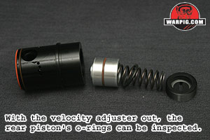
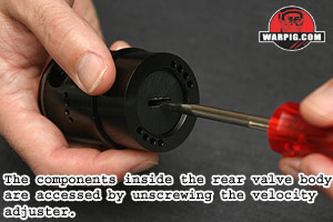 Inside
the rear valve body is the velocity control piston, its spring, bumper
o-ring and the velocity control screw. The velocity control screw
is better described as a disk than a screw, due to its shape. Unscrewing
it from the back of the rear valve body with a straight slot screwdriver
is all that is needed to slide out all of the bodys internal parts, allowing
all of the o-rings to be inspected. Inside
the rear valve body is the velocity control piston, its spring, bumper
o-ring and the velocity control screw. The velocity control screw
is better described as a disk than a screw, due to its shape. Unscrewing
it from the back of the rear valve body with a straight slot screwdriver
is all that is needed to slide out all of the bodys internal parts, allowing
all of the o-rings to be inspected.
The remaining major component to be
disassembled at this point is the fuel injector, the brass valve that delivers
a squirt of propane into the back of the combustion chamber at the rear
of the pump stroke.
 This
valve is located in the front of the front valve body, and is held in place
by a C shaped snap ring. Removing it requires a pair of compressing
or reversible snap ring pliers. The rounded tips of these pliers
fit into holes on the ends of the clip, and pull them together, compressing
the clip so that it can slide out of its retaining grove. This
valve is located in the front of the front valve body, and is held in place
by a C shaped snap ring. Removing it requires a pair of compressing
or reversible snap ring pliers. The rounded tips of these pliers
fit into holes on the ends of the clip, and pull them together, compressing
the clip so that it can slide out of its retaining grove.
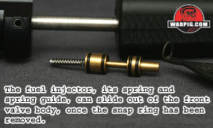 With
the clip removed the fuel injector can slide out of the front valve body
a pair of needle nosed pliers can help with this process. Along
the fuel injector are four o-rings all of which must be inspected for damage. With
the clip removed the fuel injector can slide out of the front valve body
a pair of needle nosed pliers can help with this process. Along
the fuel injector are four o-rings all of which must be inspected for damage.
WD-40, an oil that most airsmiths avoid,
due to its reputation for damaging buna o-rings, is what Tippmann recommends
for cleaning the interior surfaces of the combustion chamber, and the ends
of the valve bodies. It is what they recommend as a cleaner not
a lubricant however, and once cleaned up it is their own brand of paintgun
oil that they recommend for lubrication. All of the o-rings can be
lubricated by a very light coating of paintgun oil. In addition,
white lithium grease topped by a light coat of oil is the recommended lubricant
for the large black seals around the exhaust piston. It is important
to be careful here, as excessive grease and or oil can foul the C3s spark
plug, preventing proper ignition.
Reassembly of the C3 is mostly a reverse
of the disassembly process. The valve bodies are assembled and fitted
into the exhaust chamber with the barrel seal locking the rear valve body
in. The ground wire must be re-attached to the exhaust chamber, the
spark plug snugged into position and the propane line fitted into the front
valve body. To get the barrel seals o-ring into proper shape it
is easier to place the barrel in place (with its bolt inside, connecting
rod hole aligned with its slot,) working the o-ring into position before
closing and bolting the receiver halves. The transfer tube bajo bolts
can then be screwed back into place carefully as to avoid cross threading,
and propane regulator and its adapter screwed into place. The linkage
arm fits into the bolt, and then the barrel must be snugged backward into
its final position, checking with a finger to be certain that its breech
opening is properly aligned with the feedneck before tightening the top
front receiver bolt locking the barrel in place. The front end of
the linkage arm is finally locked into the pump by sliding the underbarrel
tube back in place and securing it with its push pin. The rear cap
can be pushed into place after the receiver is reassembled. The battery
can then be reinstalled and covered with the left grip.
Upon completion of reassembly, pulling
the trigger should cause the ignition system to fire, which can be easily
heard, confirming that it is working. A few minute after re-inserting
a propane cylinder (which should be done out doors) a detectable smell
of propane odorant (which is normal within a minute or so of installing
or removing the cylinder) will be a sign of a propane leak and should be
investigated.
Continue to Testing |