|
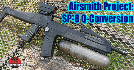
Airsmith Project:
SP-8 Q Conversion
by Bill Mills - Photos by Dawn Mills - May 2007
Page 1 Page 2
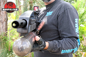
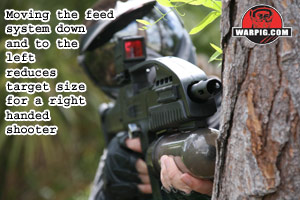
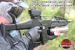 With the Warp Feed, Q-Loader and newer force-feed loader technologies which are not gravity dependent, players are getting more configuration options than ever, rather than being stuck with a hopper stitting on top of their marker. From a practical aspect, a hopper on top reduces visibility while firing, and creates additional target area when leaning out from cover. From a style aspect, many woods and scenario oriented players want their marker to look more like something from a military or sci-fi movie than an NXL field. With the Warp Feed, Q-Loader and newer force-feed loader technologies which are not gravity dependent, players are getting more configuration options than ever, rather than being stuck with a hopper stitting on top of their marker. From a practical aspect, a hopper on top reduces visibility while firing, and creates additional target area when leaning out from cover. From a style aspect, many woods and scenario oriented players want their marker to look more like something from a military or sci-fi movie than an NXL field.
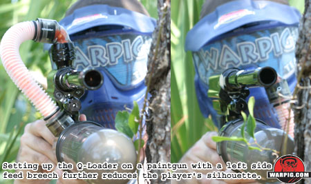
While the current crop of “low loaders” will work with almost any marker, most paintgun designers build with mainstream, up top hoppers in mind – very few commercial paintguns have been built with side or bottom feed breeches. This means that switching to a low profile feed system still often leaves feed hoses and other parts sticking off the top and or outer side of the marker.
The Smart Parts Ion holds a fair amount of potential for side feed conversion, since its receiver is nearly radially symmetrical. In fact, the gas input and mount screw in the rear of the receiver are on a pivot, meaning that tilting the receiver to the left or right would merely be a matter of creating new air ports and mount screw holes on the receiver's front half – the body breech, and of course modifying the plastic body cover to make room for the feed neck.
 Arguably, the Smart Parts SP-8 seems an even more prime candidate for side feed conversion, as the internal receiver is the same as the Ion, but it is aesthetically styled for the milsim/scenario player. Moreover, as the SP-8 receiver's outer shell is made of polymer (the $5 advertising word for durable plastic) which means it can be modified with great ease compared to aluminum – even with hand tools. Arguably, the Smart Parts SP-8 seems an even more prime candidate for side feed conversion, as the internal receiver is the same as the Ion, but it is aesthetically styled for the milsim/scenario player. Moreover, as the SP-8 receiver's outer shell is made of polymer (the $5 advertising word for durable plastic) which means it can be modified with great ease compared to aluminum – even with hand tools.
 This article should not be considered a complete set of conversion instructions for the novice, as several of the processes involved require mechanical skill and experience. Rather it is the documentation of an SP-8 side feed conversion and Q-Loader setup that may inspire experienced airsmiths to build similar custom conversions. It should also be noted that the changes to be made are radical enough to completely void the marker's warranty, and have not been reviewed or approved by Smart Parts. However, only three parts require modification – the body breech, feedneck and the left upper receiver – meaning that through the purchase of replacement parts, a botched conversion can be fixed, or a spare set-up can be ready to convert back between the stock angled feed, or left side low feed. This article should not be considered a complete set of conversion instructions for the novice, as several of the processes involved require mechanical skill and experience. Rather it is the documentation of an SP-8 side feed conversion and Q-Loader setup that may inspire experienced airsmiths to build similar custom conversions. It should also be noted that the changes to be made are radical enough to completely void the marker's warranty, and have not been reviewed or approved by Smart Parts. However, only three parts require modification – the body breech, feedneck and the left upper receiver – meaning that through the purchase of replacement parts, a botched conversion can be fixed, or a spare set-up can be ready to convert back between the stock angled feed, or left side low feed.
Conversion began with disassembly of the SP-8 and removal of the ball detents, Vision board and o-rings from the body breech. Rotating the body breech would require a new hole for the front grip screw, and a new hole for the front banjo fitting, both of which would be facing like the original holes, after the breech was rotated. Upon close inspection it was discovered that one of the ball detent holes would be in the way of the front grip frame screw hole, if the body breech were rotated 90 degrees to feed straight out to the left.
Placing the screw hole as close to the ball detent opening as possible would mean that the feed port would be slightly lower than horizontal, and the paint would not just feed across into it, but rather up into it. Since the Q-Loader maintains a constant spring pressure on the stack of paintballs, this was not expected to cause a problem.
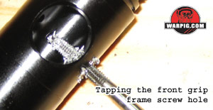
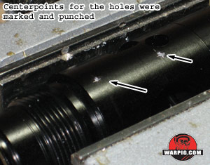 Using a strip of tape around the body breech, to ensure the correct positioning from front to back, the center points for the two new holes were marked by scratching into the anodizing with a machinist's scribe, and then center punched for drilling. Both holes are threaded for 10-32 size screws. Using a strip of tape around the body breech, to ensure the correct positioning from front to back, the center points for the two new holes were marked by scratching into the anodizing with a machinist's scribe, and then center punched for drilling. Both holes are threaded for 10-32 size screws.
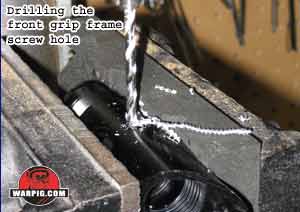 The screw hole for the grip frame screw is straightforward, it was drilled and tapped in 10-32 [Author's Confession – I rarely consult drill size charts – but rather eyeball the size of drill needed by comparing it to the inner thread width on the tap.] The screw hole for the grip frame screw is straightforward, it was drilled and tapped in 10-32 [Author's Confession – I rarely consult drill size charts – but rather eyeball the size of drill needed by comparing it to the inner thread width on the tap.]
 The hole for the banjo bolt however is more complex. It has a narrow hole that goes all the way through, and is wide enough for the 10-32 banjo bolt for only a portion of its depth. The narrow hole at the bottom ensures that gas only is fed to the front side of the bolt's center o-ring. To complicate matters, the hole is slightly off-center – though exact placement left to right is not critical, because there is room for the banjo bolt within the grip frame – and the surface around it is milled flat in order for the banjo-bolt o-ring to obtain a good seal. The hole for the banjo bolt however is more complex. It has a narrow hole that goes all the way through, and is wide enough for the 10-32 banjo bolt for only a portion of its depth. The narrow hole at the bottom ensures that gas only is fed to the front side of the bolt's center o-ring. To complicate matters, the hole is slightly off-center – though exact placement left to right is not critical, because there is room for the banjo bolt within the grip frame – and the surface around it is milled flat in order for the banjo-bolt o-ring to obtain a good seal.
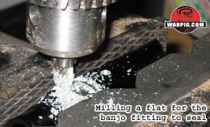 A drill bit was matched first to the through-hole, and that was drilled straight through the wall of the body breech, to allow for proper centering. Then the flat surface was milled into the receiver [Author's confession – although I do not have a proper mill, an X-Y adjustable vise allows for small scale milling projects to be tackled with a drill press and appropriate dremel or mill bits.] A drill bit was matched first to the through-hole, and that was drilled straight through the wall of the body breech, to allow for proper centering. Then the flat surface was milled into the receiver [Author's confession – although I do not have a proper mill, an X-Y adjustable vise allows for small scale milling projects to be tackled with a drill press and appropriate dremel or mill bits.]
Finally the full diameter hole was drilled, with the depth limiter on the drill press being adjusted beforehand to ensure that a 1mm wall of aluminum was left at the bottom of the hole, rather than drilling right through. Additionally the depth limit was marked on the drill bit with a wrap of duct-tape as an extra precaution.
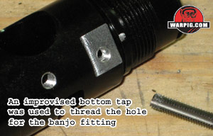 Because of the hole's shallow depth to bottom, a regular 10-32 tap with its tapered sides, could not be used to thread the hole. It would run into the bottom of the hole, before its full width teeth had cut into the sides. This is a task for a bottom-tap, but unfortunately that is a tool not stocked by most of the hardware and tool suppliers around Palm Bay, Florida. With a little ingenuity, a standard 10-32 tap was converted to a bottom tap by grinding off its tapered end with a bench grinder. Tapping of the hole was then started with a standard tap to ensure square thread alignment, and then finished with the bottom tap. Because of the hole's shallow depth to bottom, a regular 10-32 tap with its tapered sides, could not be used to thread the hole. It would run into the bottom of the hole, before its full width teeth had cut into the sides. This is a task for a bottom-tap, but unfortunately that is a tool not stocked by most of the hardware and tool suppliers around Palm Bay, Florida. With a little ingenuity, a standard 10-32 tap was converted to a bottom tap by grinding off its tapered end with a bench grinder. Tapping of the hole was then started with a standard tap to ensure square thread alignment, and then finished with the bottom tap.
The interior edges of both new holes were carefully checked and burrs broken free with a machinist scribe. The work of the side feed would be for naught if a rough edge started cutting o-rings, or bursting paintballs in the breech.
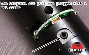 As the final steps of completing the body breech conversion, a short 10-32 set screw was treated with Locktite 242 thread-locker compound and screwed into the original forward gas port to seal it off, and the two internal and two external body breech o-rings were reinstalled. As the final steps of completing the body breech conversion, a short 10-32 set screw was treated with Locktite 242 thread-locker compound and screwed into the original forward gas port to seal it off, and the two internal and two external body breech o-rings were reinstalled.
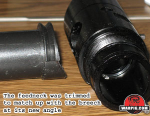 The SP-8's feedneck attaches to the outer receiver, rather than the body breech, and guides paint into the breech. With the new breech position, the inner face of the feedneck needed to be reshaped in order to fit flush against the breech. This was achieved by progressive test fittings, and simple carving with a utility knife. After each test fitting, whichever part of the feedneck pressed against the body breech was cut away, until the two parts mated together. The SP-8's feedneck attaches to the outer receiver, rather than the body breech, and guides paint into the breech. With the new breech position, the inner face of the feedneck needed to be reshaped in order to fit flush against the breech. This was achieved by progressive test fittings, and simple carving with a utility knife. After each test fitting, whichever part of the feedneck pressed against the body breech was cut away, until the two parts mated together.
In its stock placement, the feedneck needs to be lengthy, to allow room for an elbow and hopper jutting out from the receiver. In the side placement, not as much length would be needed, so it was trimmed down to a shorter length, by cutting its outer end off with a miter saw, and cleaning the end with sandpaper.
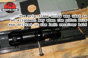 Next the left upper receiver half would need to be drilled and cut so that the feedneck could be fitted through it. One of the grip frame screws was fitted into its new hole in the body breech and was used to properly align the body breech in the right half of the upper receiver. Next the left upper receiver half would need to be drilled and cut so that the feedneck could be fitted through it. One of the grip frame screws was fitted into its new hole in the body breech and was used to properly align the body breech in the right half of the upper receiver.
The left half of the upper receiver was masked with duct tape to avoid accidental damage and scratches. It was then mated up to the right upper receiver half, and the approximate center point for the new feed port was marked. The left half was removed, and drilled at the center point with a 13/16” spade bit.
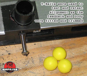 The new hole was smaller than would be needed. It was then sized and shaped through progressive test fitting of the upper receiver halves, the feedneck and the body breech, with the grip frame screw used again to ensure that the body breech was aligned in its correct position. As the fit grew closer to completion, alignment of the feedneck and body breech was regularly checked by dropping Rufus Dawg T-Ball target practice paintballs through, and making sure they rolled from the feedneck into the breech without binding. The new hole was smaller than would be needed. It was then sized and shaped through progressive test fitting of the upper receiver halves, the feedneck and the body breech, with the grip frame screw used again to ensure that the body breech was aligned in its correct position. As the fit grew closer to completion, alignment of the feedneck and body breech was regularly checked by dropping Rufus Dawg T-Ball target practice paintballs through, and making sure they rolled from the feedneck into the breech without binding.
During construction it was noticed that in the new arrangement, the Vision eye wires would now plug into their circuit board on the right side of the receiver, not the bottom. The presented a minor problem. During disassembly of a standard SP-8 the Vision wiring harness is easy to access. It is unplugged from the Vision board allowing the inner receiver assembly to slide out of the upper receiver for cleaning and maintenance.
In the new arrangement, the upper receiver would have to be disassembled in order to unplug the wires and get to the internals. While this would not be a major technical challenge, it does pose a minor issue.
At its top, the sight rail and round activator serve to clamp it together, but at the rear a pair of screws hold it tight. These screws go through one half, and into plastic screw holes in the other. They do a great job of holding tight, but if they are removed and reinserted many times, they will eventually strip out their screw holes.
 The upper receiver is not designed to be disassembled and reassembled many times. The SP-8 manual says, “The only time you will need to to separate the two halves of the receiver is when you purchase a color body kit or need to replace a damaged part.” Since this modification will require disassembly of the upper receiver for normal maintenance, another modification was in order – one which some players may want to undertake even if not doing a feedneck conversion. The upper receiver is not designed to be disassembled and reassembled many times. The SP-8 manual says, “The only time you will need to to separate the two halves of the receiver is when you purchase a color body kit or need to replace a damaged part.” Since this modification will require disassembly of the upper receiver for normal maintenance, another modification was in order – one which some players may want to undertake even if not doing a feedneck conversion.
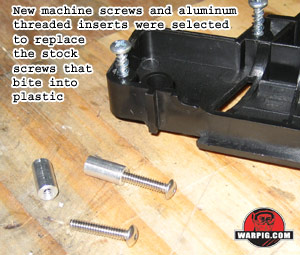
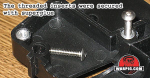 A set of 6-32 screws and 1/2” long 6-32 threaded inserts were obtained at a local hardware store. The screw holes in the left upper receiver half were drilled out to match the outer diameter of the threaded inserts. The inserts were then given a light coating of cyanoacrylate superglue, and press-fit into place [Author's note – Along with a little bit of finger tip – that stuff bonds skin instantly!] A set of 6-32 screws and 1/2” long 6-32 threaded inserts were obtained at a local hardware store. The screw holes in the left upper receiver half were drilled out to match the outer diameter of the threaded inserts. The inserts were then given a light coating of cyanoacrylate superglue, and press-fit into place [Author's note – Along with a little bit of finger tip – that stuff bonds skin instantly!]
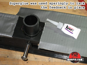 Next, a very small amount of cyanoacrylate superglue was used to tack the feedneck in position, with the two upper receiver halves fit together and the body breech inside, still aligned with the grip frame screw. Extreme care was taken not to use excess glue, as that could run down and lock the two receiver halves together, or bond the feedneck to the body breech. The glue would not be used to permanently mount the feedneck – only to hold it in place for the next step. Next, a very small amount of cyanoacrylate superglue was used to tack the feedneck in position, with the two upper receiver halves fit together and the body breech inside, still aligned with the grip frame screw. Extreme care was taken not to use excess glue, as that could run down and lock the two receiver halves together, or bond the feedneck to the body breech. The glue would not be used to permanently mount the feedneck – only to hold it in place for the next step.
The fit of all parts was again verified by test feeding target balls. At this point, if there was an alignment issue, the small points of tacking glue used would allow the feedneck to be broken free and realigned. Fortunately, the fit worked on the first go round.
The left upper receiver half was re-masked, even closer to the feedneck, and the feedneck was masked as well, with duct tape. While not a necessary step it was decided to additionally modify the right upper receiver half, filling in the now empty feed port. The inside surface of the feedport was taped over with duct tape.
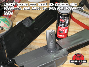 PC-7 two part epoxy paste was then used to secure and fillet the feedneck to the left upper receiver half, and to fill in the feed port on the right half. The Epoxy paste was forced down into the gaps between the feedneck and the receiver half, from the inside as well. Care was taken not to build up the inside to the point that it would prevent a proper fit with the body breech. PC-7 two part epoxy paste was then used to secure and fillet the feedneck to the left upper receiver half, and to fill in the feed port on the right half. The Epoxy paste was forced down into the gaps between the feedneck and the receiver half, from the inside as well. Care was taken not to build up the inside to the point that it would prevent a proper fit with the body breech.
Continued on Page 2.
|