Smart Parts' Ion
Disassembly
By Bill Mills - Photos
by Dawn Mills - Aug 2005
Overview
- How It Works - Disassembly
- Testing - Raw Test Data
 Field
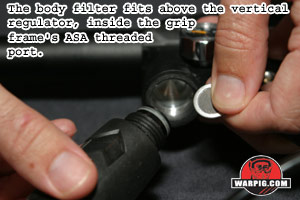
stripping the Ion is limited to removing the barrel for breech cleaning,
and removal of the vertical regulator to clean the body filter screen.
Bench stripping is a bit more involved, but due to the simplicity of the
Ions design, not overly complicated. Field
stripping the Ion is limited to removing the barrel for breech cleaning,
and removal of the vertical regulator to clean the body filter screen.
Bench stripping is a bit more involved, but due to the simplicity of the
Ions design, not overly complicated.
 Removing
the receiver from the grip frame is necessary to access the bolt.
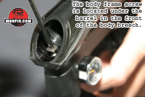
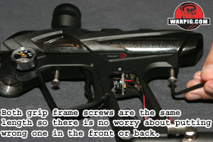
This begins by removing the barrel. After a the body frame screw
is removed from beneath where the barrel sits, the two grip frame screws
can be removed from the front and back of the grip frame. Removing
the receiver from the grip frame is necessary to access the bolt.
This begins by removing the barrel. After a the body frame screw
is removed from beneath where the barrel sits, the two grip frame screws
can be removed from the front and back of the grip frame.
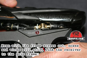
At this point, the receiver and grip
frame will be interconnected, by pneumatics hoses. The hoses mate
with the receiver using right angle banjo bolt (a hollow gas-through bolt)
assemblies.
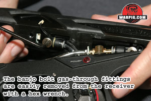
Using a hex wrench both the front and
rear banjo bolts can be unscrewed from the receiver, and the wiring harness
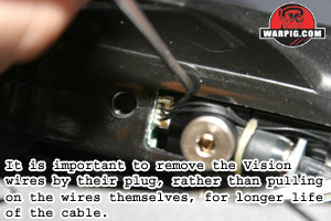
unplugged from the Vision circuit board. It is important that the
wring harness be pulled out by its connector, rather than tugging on the
wires which might pull them loose.
 With
the wires and hoses free the receiver can be handled separately from the
grip frame. The body cover simply slides off of the receiver, and
can be cleaned or swapped out for a different color. On the right
hand side of the body cover, inside, near the breech is a reflective sticker.
It is important that this sticker remain in place, as it is necessary for
proper performance of the Vision system. With
the wires and hoses free the receiver can be handled separately from the
grip frame. The body cover simply slides off of the receiver, and
can be cleaned or swapped out for a different color. On the right
hand side of the body cover, inside, near the breech is a reflective sticker.
It is important that this sticker remain in place, as it is necessary for
proper performance of the Vision system.
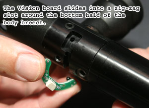 With
the body cover removed, care must be taken not to drop the Vision circuit
board. This C shaped board holds the infra-red emitter and detector
used to detect the presence of a paintball in the breech. The board
itself lifts easily out of its zig-zagged slot in the bottom of the body
breech. At this point a rolled piece of paper towel, or cotton swab
can be used to clean out the openings for the Vision eyes. With
the body cover removed, care must be taken not to drop the Vision circuit
board. This C shaped board holds the infra-red emitter and detector
used to detect the presence of a paintball in the breech. The board
itself lifts easily out of its zig-zagged slot in the bottom of the body
breech. At this point a rolled piece of paper towel, or cotton swab
can be used to clean out the openings for the Vision eyes.
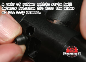
Similarly, the rubber-like nubbin style
ball detents can be pushed out and cleaned.
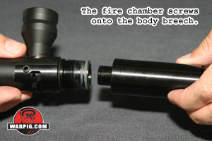
The fire chamber unscrews from the body
breech. If it is fitting too tightly to unscrew by hand, the rear
of the fire chamber has wrench flats where an adjustable wrench can get
the job done.
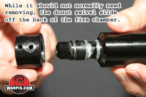
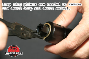 On
the rear of the fire chamber, held in place by a snap ring is the swivel
donut, a cylinder that is able to swivel. The swivel donut allows
the rear grip frame screw hole and rear gas feed and banjo bolt threads
to line up with the grip frame. Standard methods for machining threads
like those linking the fire chamber and body breech dont allow for parts
to line up. On
the rear of the fire chamber, held in place by a snap ring is the swivel
donut, a cylinder that is able to swivel. The swivel donut allows
the rear grip frame screw hole and rear gas feed and banjo bolt threads
to line up with the grip frame. Standard methods for machining threads
like those linking the fire chamber and body breech dont allow for parts
to line up.
 If
the screw and gas port holes were drilled straight into the fire chamber,
this would have to be done when it was assembled to the body breech.
While that might work, huge problems would arise because the fire chamber
from one Ion would end up with misaligned holes if it were fitted to a
different body breech. Long time players may remember the Air Power
Vector which required custom drilled gas ports when a replacement valve
was installed, for this very reason. The swiveling donut on the Ion
elegantly solves this problem without the need for more costly and time
consuming indexed threading. In typical maintenance, the swivel donut
will not need to be removed. If
the screw and gas port holes were drilled straight into the fire chamber,
this would have to be done when it was assembled to the body breech.
While that might work, huge problems would arise because the fire chamber
from one Ion would end up with misaligned holes if it were fitted to a
different body breech. Long time players may remember the Air Power
Vector which required custom drilled gas ports when a replacement valve
was installed, for this very reason. The swiveling donut on the Ion
elegantly solves this problem without the need for more costly and time
consuming indexed threading. In typical maintenance, the swivel donut
will not need to be removed.
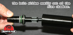 When
the breech body is removed from the fire chamber, the bolt will go with
it. Gripping the bolt face by hand is all that is needed to pull
it out of the fire chamber. With the bolt will come the bolt stop. When
the breech body is removed from the fire chamber, the bolt will go with
it. Gripping the bolt face by hand is all that is needed to pull
it out of the fire chamber. With the bolt will come the bolt stop.
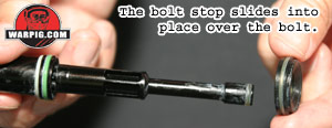
It is important to note the orientation
of the bolt stop. It is narrower on one side of its o-ring than the
other, than the other. If the bolt stop is reinstalled backwards,
the fire chamber will not be able to screw all the way onto the body breech,
and the receiver will no longer line up correctly with the screw holes
in the grip frame.
 The
force with which the Ions bolt moves forward depends on two things, the
pressure of the gas in the fire chamber and the rear surface area of the
bolt. Because the fire chambers air input is on a part that swivels,
and the bolt stop is a removable part, the Ion is open to aftermarket bolt
manufacturers to experiment with various possibilities, both in changing
the pressure of gas fed to the fire chamber separate to that fed through
the solenoid valve, and in varying bolt diameter to compensate for the
pressure change and still allow proper bolt movement. The
force with which the Ions bolt moves forward depends on two things, the
pressure of the gas in the fire chamber and the rear surface area of the
bolt. Because the fire chambers air input is on a part that swivels,
and the bolt stop is a removable part, the Ion is open to aftermarket bolt
manufacturers to experiment with various possibilities, both in changing
the pressure of gas fed to the fire chamber separate to that fed through
the solenoid valve, and in varying bolt diameter to compensate for the
pressure change and still allow proper bolt movement.
 After
cleaning, the Ions receiver parts re-assemble in a reverse of their disassembly
procedure. Shocker grease is the Smart Parts only recommended lubricant
for the seals in the receiver, and it is important to note that over-lubricating
can cause performance problems. After
cleaning, the Ions receiver parts re-assemble in a reverse of their disassembly
procedure. Shocker grease is the Smart Parts only recommended lubricant
for the seals in the receiver, and it is important to note that over-lubricating
can cause performance problems.
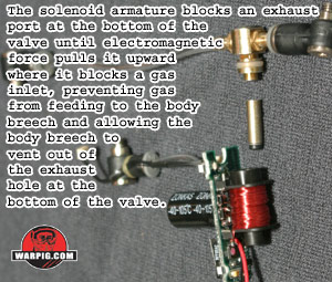
While the receiver is off the grip frame
the Ions circuit board can be slid out of the top of the grip. Because
of the size of the solenoid valve used, it can be cleaned and checked with
relative ease compared to the miniscule valves found in most electropneumatic
paintball guns.
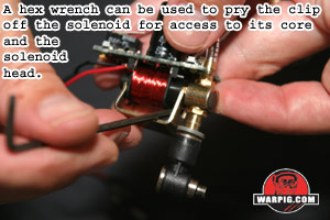 A
metal bracket holds the solenoid together, and is clipped in place by spring
tension. Care must be taken when removing the clip, not to damage
the exposed wires of the solenoid coil. A small hex wrench or tweaker
can be used to pry between the clip and the section of black plastic coil
frame at the top of the solenoid. A
metal bracket holds the solenoid together, and is clipped in place by spring
tension. Care must be taken when removing the clip, not to damage
the exposed wires of the solenoid coil. A small hex wrench or tweaker
can be used to pry between the clip and the section of black plastic coil
frame at the top of the solenoid.
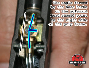 With
the clip removed, the head of the solenoid can be removed and the core
slides easily out of the coil. When reassembling the solenoid, its
head must be oriented correctly. The two hose barbs on the head are
not perfectly aligned, they form a slight angle. This angle should
point, like an arrow, toward the right side of the grip frame when the
circuit board is in place. With
the clip removed, the head of the solenoid can be removed and the core
slides easily out of the coil. When reassembling the solenoid, its
head must be oriented correctly. The two hose barbs on the head are
not perfectly aligned, they form a slight angle. This angle should
point, like an arrow, toward the right side of the grip frame when the
circuit board is in place.
Continue to
TESTING |