Related Resources:
Basic Stamps:
Basic
Stamp FAQ
Parallax,
Inc.
Marlin
P Jones
SLI-OEM:
WIRZ.com
What
do you think?
Add
your comments in WARPIG's TECH TALK FORUMS.
|
Utilizing
the Paralax Basic Stamp for paintball applications
By Bill Mills
Page 1 Page
2 Page 3
This article is
the third in a series for airsmiths who are wishing to provide custom electronic
controls for paintguns they are building or customizing. The first
article covered the basics of soldering, a critical skill for repair or
construction, while the second covered basic electronic theory and identifying
components. These articles by no means represent a comprehensive
course in electronics design and construction, but offer a springboard
to get one moving in the right direction.
This article is
not a step by step guide to building a control circuit for a paintgun.
Rather, it is intended to provide the basic circuits and programming knowledge
that one needs to design and program their own systems for their specific
applications. It is by no means a comprehensive training course
the manuals recommended should be considered required reading.
What this article will do is put the reader on the right path to make sense
of what they are reading, and highlight the key points that are applicable
to building custom paintgun circuitry. The circuits described here
can be combined with the Basic Stamp to make a full featured paintgun controller.
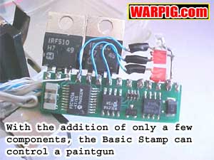 As
I had mentioned in the second article that microprocessors, while seemingly
more complex and high tech than other electronic components actually can
greatly simplify the circuitry needed for a specific task. The reason
for this is that the complexity of operation lies not in the circuits,
but in the software controlling them. This has several advantages.
For me, as someone fluent in a number high level programming languages
this is good because it put me on my home turf (note: high level doesnt
mean hard to learn it means they are easier to learn because they are
closer to written languare than to the raw numbers microprocessors understand).
It also has the distinct advantage that adding or removing, or testing
features such as a delay time between the close of a paintguns bolt and
the time it fires is simply a matter of tweaking software instead of designing
and building a new circuit. Thats a huge benefit when testing and
adjusting a prototype. It also adds greater precision. A delay
set by clock cycles in a chip is far more accurate than a delay set by
how fast a capacitor can charge, especially considering how wide the tolerances
are on most resistors as we learned in the previous article. As
I had mentioned in the second article that microprocessors, while seemingly
more complex and high tech than other electronic components actually can
greatly simplify the circuitry needed for a specific task. The reason
for this is that the complexity of operation lies not in the circuits,
but in the software controlling them. This has several advantages.
For me, as someone fluent in a number high level programming languages
this is good because it put me on my home turf (note: high level doesnt
mean hard to learn it means they are easier to learn because they are
closer to written languare than to the raw numbers microprocessors understand).
It also has the distinct advantage that adding or removing, or testing
features such as a delay time between the close of a paintguns bolt and
the time it fires is simply a matter of tweaking software instead of designing
and building a new circuit. Thats a huge benefit when testing and
adjusting a prototype. It also adds greater precision. A delay
set by clock cycles in a chip is far more accurate than a delay set by
how fast a capacitor can charge, especially considering how wide the tolerances
are on most resistors as we learned in the previous article.
 Because
the author has no method of ensuring the safety by which a custom built
paintgun can be used, all software in this article is Copyright 2002, William
R. Mills III and may not be used for anything other than controlling data
displays and LEDs as a learning project it may not be used to control
paintguns or other physical devices. Airsmiths who take the time
to learn about the Basic Stamp technology discussed here should have little
trouble writing their own programs to control customized paintguns. Because
the author has no method of ensuring the safety by which a custom built
paintgun can be used, all software in this article is Copyright 2002, William
R. Mills III and may not be used for anything other than controlling data
displays and LEDs as a learning project it may not be used to control
paintguns or other physical devices. Airsmiths who take the time
to learn about the Basic Stamp technology discussed here should have little
trouble writing their own programs to control customized paintguns.
While
select fire and full automatic modes can be very useful to an airsmith
in testing performance of valves, air and feed systems, it is not allowed
at most paintball fields, and is not planned to be allowed under the proposed
ASTM standards for paintguns. As such airsmiths would be best advised
NOT to release any firing mode but semi-automatic to their customers.
It should also be noted cheater modes paintgun modes that appear to do
one thing, while secretly providing their user with an advantage should
be avoided as they will only serve to cause field owners and event promoters
to adopt tighter restrictions against electronically controlled paintguns.
 In
late 1999 the Angel LCD was new on the market. I was eager to experiment
with microprocessors, but figured that the electronic circuitry required
to use them in a paintgun would be beyond my capabilities. I had
seen the Parallax Basic Stamp in Radio Shack catalogs, and in Marlin P.
Jones catalog, and decided to give it a more thorough look. After
a brief web search I found the Parallax web site, and a number of Basic
Stamp hobbyist sites. I was pretty blown away with what I found.
The Basic Stamp isnt just a microprocessor. It is a complete programmable
multi purpose computer on a tiny little chip. It is programmed in
PBASIC, a high level programming language, and can be had at a reasonable
price. Using the Basic Stamp made my Rainmaker LCD project simple
enough that I went from no knowledge of Basic Stamps to completed Rainmaker
LCD in 3 afternoon work sessions. In
late 1999 the Angel LCD was new on the market. I was eager to experiment
with microprocessors, but figured that the electronic circuitry required
to use them in a paintgun would be beyond my capabilities. I had
seen the Parallax Basic Stamp in Radio Shack catalogs, and in Marlin P.
Jones catalog, and decided to give it a more thorough look. After
a brief web search I found the Parallax web site, and a number of Basic
Stamp hobbyist sites. I was pretty blown away with what I found.
The Basic Stamp isnt just a microprocessor. It is a complete programmable
multi purpose computer on a tiny little chip. It is programmed in
PBASIC, a high level programming language, and can be had at a reasonable
price. Using the Basic Stamp made my Rainmaker LCD project simple
enough that I went from no knowledge of Basic Stamps to completed Rainmaker
LCD in 3 afternoon work sessions.
Basic
Stamp technology
There are a few
versions of the Basic Stamp available. The original Revision D Basic
Stamp is kind of bulky compared to the more popular and modern Basic Stamp
IC (which I will simply call the Basic Stamp, BS1-IC). There is also
the Basic Stamp II which features twice the input/output connections of
the IC, 512 times more memory, and is available in faster versions as well.
All versions of the Basic Stamp are programmed with the same PBASIC instruction
set (though the BS2 features some additional commands) making it easy to
expand from one to another as more power is needed.
 I
started off with the Basic Stamp IC, due to its lower cost and smaller
size, and found it is more than powerful enough to handle most of the needs
in a paintgun. A paintgun with extensive LCD text menus might be
better suited to be driven by the BS2 due to its much roomier memory.
The BS1-IC is available in a variety of forms. It can be purchased
stand-alone for around $30 (and cheaper by the dozen) or in a kit which
includes a stamp, a carrier board, manual, programming cable, and MS-DOS
PBASIC editor and compiler software that sells for about $100. Diagrams
for the programming cable, the programming software, and even the documentation
are all available online free of charge, but the kit definitely makes getting
started with Basic Stamps a lot easier. I
started off with the Basic Stamp IC, due to its lower cost and smaller
size, and found it is more than powerful enough to handle most of the needs
in a paintgun. A paintgun with extensive LCD text menus might be
better suited to be driven by the BS2 due to its much roomier memory.
The BS1-IC is available in a variety of forms. It can be purchased
stand-alone for around $30 (and cheaper by the dozen) or in a kit which
includes a stamp, a carrier board, manual, programming cable, and MS-DOS
PBASIC editor and compiler software that sells for about $100. Diagrams
for the programming cable, the programming software, and even the documentation
are all available online free of charge, but the kit definitely makes getting
started with Basic Stamps a lot easier.
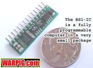
 The
BS1-IC is a circuit board roughly 1.5 by 0.25 in size, with a row of
14 connector pins on one edge allowing it to plug into a socket.
On board the BS1-IC are all of the components it needs to operate.
This leaves function specific circuits up to the user. Very simple
circuits can be built leading to the Stamps I/O pins to either send input
signals to it, or to control components like solenoid valves with it. The
BS1-IC is a circuit board roughly 1.5 by 0.25 in size, with a row of
14 connector pins on one edge allowing it to plug into a socket.
On board the BS1-IC are all of the components it needs to operate.
This leaves function specific circuits up to the user. Very simple
circuits can be built leading to the Stamps I/O pins to either send input
signals to it, or to control components like solenoid valves with it.
|
Going down
the Stamp, the pins serve the following functions:
Pin
1 PWR - Power This is where the + voltage
is applied to the Stamp. The BS1-IC operates on +5volts. This
pin connects to the input of a fixed output voltage regulator, and accepts
input voltages from 6 to 15 volts. A 9 volt battery then becomes
a natural choice as a power source for the Stamp, as it can run for a VERY
long time before it will drop down to only 6 volts.
Pin
2 GND - System Ground This connects to
the connection of the power source, and the chassis if a frame ground
is to be used in the application. When a programming cable is connected
to the Stamp, it must link Pin 2 to Pin 25 on the computers parallel port.
Pin
3 - PCO PC Out The programming cable connects
this pin to Pin 11 (Busy) of the computers parallel port.
Pin
4 PCI PC In The programming cable connects this pin to Pin 2 (D0)
of the computers parallel port.
Pin
5 - +5v 5volt in/out This is the output
of the onboard voltage regulator. If youre using a battery to power
the Stamp on Pin 1, you can use Pin 5 as a regulated +5v power source for
circuits that are connected to the Stamp. Pin5 can also be used to
power the stamp by connecting a +5v regulated power source to it instead
of Pin1 (its easier just to use batteries linked to Pin 1). It is
important to note that the onboard regulator is not very heavy duty, and
the output of Pin 5 should not be used as a power source to drive things
like solenoids or high current light bulbs they should get their power
from the battery direct, or through another voltage regulator.
Pin
6 RES Reset When the power supplied
to the basic stamp drops below +4v, this pin goes low to reset the BS1-IC.
You can force this pin low by shorting it to ground, and manually reset
the Stamp, just like the reset button on a PC.
Pins
7 to 14 P0 to P7 General Purpose I/O pins
These pins are how the Stamp communicates. They can accept button
(or trigger) presses, read analog voltage values, give pulsed output (which
can generate sound waves at specific tones, or control the speed of DC
motors), read or send serial data (to communicate with other computers
or LCD displays) or simply give high/low output (to turn on or off compnents
like LEDs or solenoids). The abilities of these pins is mainly limited
by what circuits you attach to them. It is also important to not
that these pins should not be used to drive circuits with heavy loads
they should never be used to deliver more than 40mA of current combined.
Instead let them do things like control a transistor that will carry the
load. |
High is not about drugs
There are a couple
of more terms we should know before going on high and low. When
dealing with computer components we have two binary states on and off,
the simple ones and zeroes computers understand at their simplest level.
Since the Stamp runs at +5 volts, a high or on is going to mean +5
volts in a circuit, while a low or off will simply mean no, or minimal
voltage in the circuit.
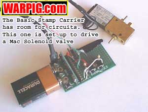
The BS1-IC carrier
This is really a nifty board, and it is included in the Basic Stamp starter
kit. It has a socket where a BS1-IC can plug into it, a socket for
the PC programming cable to plug in, a reset button (wired to drive Pin
6 low by shorting it to ground) battery clips to attach to a 9v battery,
and a perforated board area where circuits can be prototyped and linked
to the socket connectors where they can link to the BS1-IC. The Carrier
is definitely a good tool to have on hand when learning to use the Stamp.
The first circuits I built onto my Carrier board were a pair of LED indicators
and a pair of push buttons.
Programming
the Basic Stamp
OK, if youve
never written any computer programs or scripts before, there might be a
few hurdles to jump here. This is a very good reason to pick up the
Basic Stamp Manual it does a great job of explaining how to program the
Stamp, as well as give example circuits and programs every step of the
way.
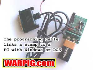 The
programs for the Basic Stamp are written in the PBASIC editor program that
runs on a PC in MS-DOS. When a program is ready for testing on the
Stamp, the Stamp is connected to power, and the programming cable is used
to link the PC to the stamp. The program is then Run (ctrl-R from
the PBASIC software see the Stamp manual for full instructions).
When the program is run, the Stamp editor compiles it from the English
PBASIC commands that make sense to us into a series of numbers that will
make sense to the PBASIC interpreter chip on the Basic Stamp. If
there are any fatal errors in the way the program was written (misspelled
commands, etc.) the editor will give an error message explaining the problem.
Otherwise, the program is then fed via the cable into the EEPROM (Electronically
Eraseable Programmable Read Only Memory) on the Stamp, and it will begin
running. Now that the EEPROM has been programmed, the Stamp will
have our commands in it, and will begin running our program whenever it
is supplied with power, even if it is no longer connected to the PC with
the programming cable. The
programs for the Basic Stamp are written in the PBASIC editor program that
runs on a PC in MS-DOS. When a program is ready for testing on the
Stamp, the Stamp is connected to power, and the programming cable is used
to link the PC to the stamp. The program is then Run (ctrl-R from
the PBASIC software see the Stamp manual for full instructions).
When the program is run, the Stamp editor compiles it from the English
PBASIC commands that make sense to us into a series of numbers that will
make sense to the PBASIC interpreter chip on the Basic Stamp. If
there are any fatal errors in the way the program was written (misspelled
commands, etc.) the editor will give an error message explaining the problem.
Otherwise, the program is then fed via the cable into the EEPROM (Electronically
Eraseable Programmable Read Only Memory) on the Stamp, and it will begin
running. Now that the EEPROM has been programmed, the Stamp will
have our commands in it, and will begin running our program whenever it
is supplied with power, even if it is no longer connected to the PC with
the programming cable.
When programming
in a high level language we are simply giving the computer a list of things
we want it to do. The Stamp will go down that list, and do the items
in order. Sometimes the items on the list will tell the computer
to go to another place in the list. Heres an example of what I mean
in a list of instructions you might give to a paintball player.
Step
1 Put on your goggles
Step
2 Walk up to the chronograph
Step
3 Fire the paintgun over the chronograph
Step
4 Read the number off of the chronograph
Step
5 If the number on the chronograph is higher
than 300 adjust the paintgun to a slightly lower velocity then go back
to Step 3
Step
6 Go on to the field and play |
Continued on Page
2 |