  |
|
|
|
|
|
|
| |
|
|
|
|
|
|

What
do you think?
|
By Bill Mills Since weve done
everything modularly, its much easier to make changes. For example,
if we wanted to drive a paintgun with a pair of solenoid valves, like an
Autococker conversion, or the conversion I did on a PMI-1, we need to change
the Fire subroutine. Assuming we used I/O Pin 2 to control a MOSFET
circuit driving the solenoid that controlled a ram to trip the paintguns
sear, we could put a MOSFET circuit on I/O Pin 3 to control a solenoid
valve that moves the ram and bolt.
'###### Firing subroutine for a two solenoid
design
It may be necessary to add another delay. I found, when I fired up my PMI-1 conversion that it worked great, for the first shot, but if I rapid fired it would cock but not shoot. I discovered that after moving the bolt back and forth, the low pressure regulator needed a few milliseconds to recharge enough gas pressure to trip the sear. I solved this by adding a pause command right after closing the bolt in the firing subroutine.
With the SLI-OEM connected to the same ground as the Stamp, and receiving power, all it needs is a wire running from a Stamp pin to its serial input. Looking at connector J1 on the SLI-OEM board from the front, J1 will be a series of 10 holes in two rows of 5 on the right. We can ignore the left row, and concentrate on the right side pins. Looking top to bottom, pin 1 should get +5v, pin 2 goes to ground, pin 3 goes to the Stamp, pin 4 to ground, and pin 5 goes to +5v. For our example lets run the SLI-OEM serial line to the Stamps pin 12, which is I/O pin 5. This would still leave us with I/O pin 4 available and unused.
Serout 5,n2400,(10,"www.WARPIG.com")
The serout command does what its name implies it sends serial data out of the Basic Stamp. The first argument is the number of the pin on which the data should be sent, in this case I/O pin 5, where weve connected to the SLI-OEM. N2400 means that the data should be sent at 2400 bits per second, inverted polarity. This value MUST match the settings on the dip switches of the SLI-OEM, or other serial device the with which the Stamp is communicating. The Stamp can use data rates from 300 to 2400 bps, the faster we send this data to the LCD, the less time it needs to do the job so faster is better. The argument in parentheses is the data that will be sent to the display. A single character can be specified by ASCII number, or text can be sent in quotes. Character number 10 clears the display, the WARPIG URL in quotes gets displayed. I added a short delay to the program after displaying the boot message before the program hits the Gosafe procedure. To the Gosafe procedure, right after the lines which turn off the safety/armed LED, I added the line: Serout 5,n2400,(10,"SAFE") '# Display safe mode Then to the Gosemi procedre, right after the lines which turn on the safety/armed LED, I added: Serout 5,n2400,(10,"SEMIAUTO") '# display semi-auto mode Bada-bing-bada-boom Its an LCD paintgun. Things like a shot counter are fairly simple to implement. A shot counter starts by specifying a variable to use for the counter this needs to be a word variable if you want to count more than 255 shots. This line can be added near the beginning of the program when the variables are defined: Symbol count = w2 '# define w2 for the shot counter Then, each time the paintgun is fired, the counter should be increased by one and displayed on the LCD This is done by adding the following lines to the Fire subroutine right before the return command. Count=count+1 '# increment
shot counter
This will show the shot count each time the trigger is pulled. Semi-auto wont be displayed again until the mode button is pressed cycling back to safe mode and then to semi-auto again. An important note about the LCD displays. Most PBBASIC commands take up one or two bytes of EEPROM memory, yet each letter displayed on the LCD will take up a whole byte. Adding LCD text messages can quickly eat away at the 256 bytes of memory available on the BS1-IC. In my experience a program to allow 3 firing modes, safety mode, shot counter, and shot odometer (the total shots fired since the board was programmed) can actually take up more memory than the BS1-IC has available, and require the boot message to be dropped to make room. The Parallax Basic Stamp represents an easy way to integrate a microprocessor into real world physical applications. While it wouldnt be cost effective for a mass manufactured paintgun, its versatility and ease of programming makes it ideal for building and testing prototype paintguns or one-off custom paintguns. End Of Line. |
| Copyright © 1992-2019
Corinthian Media Services. WARPIG's webmasters can be reached through our feedback form. All articles and images are copyrighted and may not be redistributed without the written permission of their original creators and Corinthian Media Services. The WARPIG paintball page is a collection of information and pointers to sources from around the internet and other locations. As such, Corinthian Media Services makes no claims to the trustworthiness or reliability of said information. The information contained in, and referenced by WARPIG, should not be used as a substitute for safety information from trained professionals in the paintball industry. |
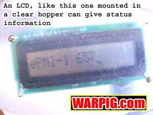 So
what about an LCD display? Alphanumeric LCDs most often have a parallel
interface, that means they need 4 or 8 data lines to communicate, and on
our BS1-IC thats not only going to hog our I/O lines, but its also going
to take a fair amount of our precious memory space. The solution
is a serial interface, which needs only a single data line to communicate.
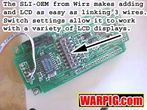
Serial LCD displays usually have a fairly hefty price tag in comparison
to parallel, but Wirz electronics makes a converter that sells for around
$20. Merlin P. Jones usually even throws in a free 8x1 LCD with the
Wirz SLI-OEM board. The SLI-OEM needs 5 volts of power, so you could
draw right from pin 5 on the Stamp to power it. I prefer to not tax
the Stamps voltage regulator, and instead mount a fixed output 5v regulator
on the SLI-OEM, and feed that with the +9v straight from the battery (or
the 18v straight off the battery pack in a Revolution). The SLI-OEM
comes with a set of instructions, and it can take a little reading to figure
out what the proper dip switch settings are for the display that it is
to be used with. The SLI-OEM must be soldered onto the back of the
LCD display which is a quick 2 or 3 minute job.
So
what about an LCD display? Alphanumeric LCDs most often have a parallel
interface, that means they need 4 or 8 data lines to communicate, and on
our BS1-IC thats not only going to hog our I/O lines, but its also going
to take a fair amount of our precious memory space. The solution
is a serial interface, which needs only a single data line to communicate.
Serial LCD displays usually have a fairly hefty price tag in comparison
to parallel, but Wirz electronics makes a converter that sells for around
$20. Merlin P. Jones usually even throws in a free 8x1 LCD with the
Wirz SLI-OEM board. The SLI-OEM needs 5 volts of power, so you could
draw right from pin 5 on the Stamp to power it. I prefer to not tax
the Stamps voltage regulator, and instead mount a fixed output 5v regulator
on the SLI-OEM, and feed that with the +9v straight from the battery (or
the 18v straight off the battery pack in a Revolution). The SLI-OEM
comes with a set of instructions, and it can take a little reading to figure
out what the proper dip switch settings are for the display that it is
to be used with. The SLI-OEM must be soldered onto the back of the
LCD display which is a quick 2 or 3 minute job.
 With
the SLI-OEM hooked up, we are set to add commands to the program to display
data. I after mixed results with the SLI-OEM and the LCD display
that Merlin P. Jones had packaged with it, that it takes a second or so
for it to boot and be ready to receive data. So, it may be necessary
to put an additional pause command in the program during the initialization
of variables to give the SLI-OEM time to get ready before the first message
is sent to it. I added the following line of code after the power
light blinks:
With
the SLI-OEM hooked up, we are set to add commands to the program to display
data. I after mixed results with the SLI-OEM and the LCD display
that Merlin P. Jones had packaged with it, that it takes a second or so
for it to boot and be ready to receive data. So, it may be necessary
to put an additional pause command in the program during the initialization
of variables to give the SLI-OEM time to get ready before the first message
is sent to it. I added the following line of code after the power
light blinks: