  |
|
|
|
|
|
|
| |
|
|
|
|
|
|
What
do you think?
|
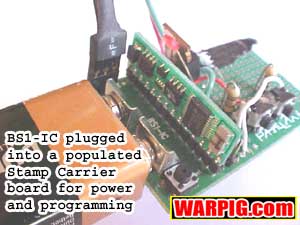
By Bill Mills In PBASIC, unlike most flavors of BASIC, we wont have to label each of our steps, unless were going to send the program there by name, like when step 5 sent the program back to Step 3 Step 3 would need to be given a name in PBASIC. Learning PBASIC is mainly about learning the commands that the interpreter understands, then putting them in the right order to do the job that we want done. Ill go over a number of commands, and some sample programs and circuits again this is just an introduction, the Basic Stamp Manual and numerous Basic Stamp resource web sites give much more complete information. Word to the bit, its a byte thang In addition to the EEPROM that holds the Stamps program, and some long term data storage, the PBASIC interpreter chip (the processor on the Stamp) has a whopping 16 bytes of Random Access Memory (RAM) that PBASIC programs can use to store and manipulate numbers. To give you an idea of the immense computer horsepower were talking about here, that is roughly one millionth of the minimum RAM a PC needs to run Windows95. The Basic Stamps RAM is broken up into various segments, some addressable as bits (which can store a value of 1 to 0) some addressable as Bytes (which can store a value of 0 to 255) and some as Words (which can store a value of 0 to 65,535. Most of these methods overlap, so its important to choose RAM variables wisely. For example Word6 is made up of Bytes 12 and 13, so you cant use Byte 12 to store a number if you are already using Word6. A table of RAM addresses is found on Page 11 of the Basic Stamp Manual.
The second Byte of Port is the Dirs Byte it gets its name for direction. All of the bits that make up this Byte determine whether the I/O pins with corresponding names are to be used for input or output. Well see some of this in our example programs. Lets get to it! Well deal with a couple of very simple circuits which are in fact, very representative of the type of things we need to run a paintgun.
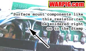
This circuit is
easy to wire on the Stamp Carrier board, though to miniaturize for use
on a paintgun, I have assembled it using a surface mount resistor soldered
right onto the base of the stamp pin, with a micro LED soldered to it,
and a short length of wire running from the LED to pin 2 on the Stamp (ground).
With the SMT resistor there was no need for the pin to stick out the side
of the stamp, so I simply cut it off to make my finished board smaller. With our LED circuit, setting the pin it is attached to high will light the LED, and setting that pin low will turn it off.
OK, with these two circuits, we can make something happen. For experimentation purposes, lets put a pushbutton circuit on Stamp pin 7 (I/O Pin0) and an LED circuit on Stamp pin 14 (I/O Pin7). In PBASIC, each line of text is used for a single command. Any time we use a symbol, everything to the right of that symbol is considered to be a comment, and is ignored by the PBASIC interpreter. Comments get stripped out of the program when it is loaded into the stamp, so they are a handy way to put notes into a program to help it make sense to a person who is studying it or modifying it. Ill use comments to add explanations or notations to programs in this article. Often, hash marks (#) are added in comments to make them more visible to the reader. The commands can also be indented with Tabs, which are also ignored by the Stamp but make the program easier to read. '#### Stamp Button Demo Program Number One
When this program
runs it is going to start by making sure that the byte variable B2 is empty.
This is important because we are going to need to let the interpreter use
B2 to operate the button command. Then we define an address point
in the program to be called Loop. Then the biggie the BUTTON command.
There are a number of ways we could check on the status of our pushbutton,
but BUTTON is really powerful, it has features built into it that save
us having to write a lot of code ourselves. Following the command
are its arguments information were giving it separated by commas.
The button command has 7 arguments:
Trigger Bounce A quick note about debouncing. When switches or pushbuttons close, they dont just turn on or off. They stutter a little bit at the beginning and end, this is called switch bounce. Its too fast for us to see, but a computer can spot it. One button push to us, can look like 2 or 3 fast presses followed by a long press followed by 2 or 3 fast presses to the computer. Debouncing cleans the signal, ignoring those little bounces at the front or Back. Simply turning off debounce is not how one writes a program for Turbo firing modes. Turbo mode requires that the software additionally has to deal with buffering the input signal from the trigger during the paintguns firing cycle. For more about Turbo mode and switch bounces, Click Here. So, what happens when our program is loaded into the Stamp? Nothing at first, until the button is pressed. Then the LED will turn on. When the button is pressed again, the button will turn off. The TOGGLE command simply changes the output value of a pin from whatever state it is in to the opposite state. If we hold the button down, after a pause, the LED will begin flashing. This is the auto repeat feature. Try changing the repeat and delay variables to see how it affects the auto-repeat performance. Remember, each time you make a change, youll need to run the program again, loading it into the Stamp by pressing <alt>R. There you have it a very simple application to show how to work with the Basic Stamp.
A MOSFET is a type of transistor. The MOSFET can handle more current than the stamp, and can provide it a reasonable level of isolation from the component it is controlling. An IFR510 MOSFET is more than ample enough to drive most small solenoid valves used in paintguns like the Rainmaker, Shocker, Bushmaster 2000, etc. The IFR510 and similar FET transistors are widely available from electronics suppliers, including Radio Shack. If driving a larger solenoid, like the one used to do the mechanical work of tripping the sear in an E-Mag, or Centerflag grip on a Spyder a larger transistor would be needed to handle the additional amperage, or multiple IFR510s could be run in series. The IFR510 sits between its load and ground. If we were using it on a paintgun to control a solenoid valve, one lead from the solenoid valve would go straight to the battery + terminal (or to an inline voltage regulator, if the battery voltage was larger than the solenoid valve could handle I usually drive MAC valves rated for 6v at 9v straight out of the battery). The other lead from the solenoid valve would go to the Drain lead of the MOSFET, while the Source leg of the MOSFET would go to ground. Its important to remember that a MOSFET goes on the ground side of the load, not on the + side. The gate of the MOSFET then is wired directly to one of the Basic Stamp I/O pins. When the pin is driven high by the software, the MOSFET allows current to flow between the Drain and Source. When the pin goes low, the MOSFET does not allow power to flow. For more info on driving high current devices, see the Basic Stamp FAQ. At this point it should be evident that the circuitry portion of an electropneumatic paintgun can be very simple to construct with the Basic Stamp and our three circuits. The minimum that is needed for a single solenoid paintgun is a basic stamp with one of our pushbuton circuits for the trigger (a pushbutton and a resistor), a MOSFET to link to the solenoid valve, and a battery. Thats all! The rest is all software, this can even run select fire, using the auto repeat feature of the BUTTON command. Adding an LCD display only requires another couple of modular components. The hard part here isnt doing the electronics, but the physical work of integrating them cleanly into the paintgun.
Really were going to want a pair of inputs for our paintgun, not just the trigger, but also a selector button that will let us switch between safe and semi-auto mode. Instead of a single LED, well use two, one to indicate that the Basic Stamp is on and getting power (and that the program inside is running OK) and one to show if we are in safe mode, or ready to fire. Well use a green LED for power, and a red one for the mode indicator. The LEDs are wired in with our LED circuit (the resistor and LED) with the green LED circuit on I/O Pin 0 (pin 7 on the Stamp), and the red on I/O Pin 1 (pin 8 on the Stamp). Well put another LED circuit the color doesnt matter on Pin 9 of the Stamp (I/0 pin 2) to simulate a MOSFET and solenoid valve circuit. This LED well call the valve LED, and it will be on to show is when the valve would be open if this circuit were wired into a paintgun. Our two pushbutton circuits well put on Stamp pins 13 and 14. The one on I/O Pin 7 we will use as our safety. The one on I/0 pin 6 will be the trigger. Selecting the right switch for the trigger in an electropneumatic paintgun is a subject for a whole article in itself. The switch needs to be an SPST normally open momentary type. From there, there are a wide range of choices for you to make that depend on the physical constraints of the paintgun, physical linkage to the trigger, and the trigger feel you want mushy, long, definitive click, short, etc. I should also add, that its a good idea to add a power switch, otherwise youd have to disconnect the battery between uses, like with the older model Shockers. A power switch is simply a SPST slide, rocker, or toggle switch spliced into the + lead from the battery clip. One terminal of the switch leads to the battery + side, while the other leads to circuitry. OK, lets get to the software. This is a straightforward sem-auto program, with safety and power light. Again as a reminder, this is a copyrighted program, and may not be used in an actual paintgun. With a light understanding of PBASIC, you should not have a problem writing your own program to meet your exact needs. '### Semi-Auto simulation Software for single
solenoid
'# Configure and set variables
'# Flash the power LED to show that the board
is working
'##### Safe mode Gosafe comes before safe
mode so we
Gosafe: '# Label the
gosafe procedure
'####### Semi-auto mode, here we have to watch
the
Gosemi: '# Thats the label
for this procedure
'###### The firing sub-routine this is where
And thats it. When the Stamp is turned on the power LED will blink a couple of times and then stay on. The mode button will select between safe and live modes, which are indicated by the safety LED. The paintgun will only fire as a semi-auto in live mode. Continued on Page 3 |
| Copyright © 1992-2019
Corinthian Media Services. WARPIG's webmasters can be reached through our feedback form. All articles and images are copyrighted and may not be redistributed without the written permission of their original creators and Corinthian Media Services. The WARPIG paintball page is a collection of information and pointers to sources from around the internet and other locations. As such, Corinthian Media Services makes no claims to the trustworthiness or reliability of said information. The information contained in, and referenced by WARPIG, should not be used as a substitute for safety information from trained professionals in the paintball industry. |
 The
first Word of RAM is called Port, and it is reserved, and while it can
be used for storing numbers. What you put into it has a big effect
on how the stamp is operating. The first Byte is called Pins, and
you can put numbers into it, or read them out of it. Its easier,
especially if you dont understand the binary number system, to address
the bits Pin0 through Pin7 individually. If I/O Pin0 for example
were hooked up to a push-button circuit that is designed to bring the pin
voltage high when the button is pressed, we would have our program watch
the value of the variable Pin0. If the button were being pressed
Pin0 would equal one, if it were not being pressed Pin0 would equal 0.
Alternatively, if we had a circuit with an LED hooked up to I/O Pin0, we
could make Pin0=1 in the software to make the pin go high and light the
LED, or make Pin0=0 to turn it off.
The
first Word of RAM is called Port, and it is reserved, and while it can
be used for storing numbers. What you put into it has a big effect
on how the stamp is operating. The first Byte is called Pins, and
you can put numbers into it, or read them out of it. Its easier,
especially if you dont understand the binary number system, to address
the bits Pin0 through Pin7 individually. If I/O Pin0 for example
were hooked up to a push-button circuit that is designed to bring the pin
voltage high when the button is pressed, we would have our program watch
the value of the variable Pin0. If the button were being pressed
Pin0 would equal one, if it were not being pressed Pin0 would equal 0.
Alternatively, if we had a circuit with an LED hooked up to I/O Pin0, we
could make Pin0=1 in the software to make the pin go high and light the
LED, or make Pin0=0 to turn it off.
 The
first circuit is an LED circuit. Its dirt simple. Well attach
a 470 ohm resistor to a Stamp I/O pin, and attach an LED linking that to
ground. Because LEDs are current specific, we must be sure the anode
of the LED is the lead that goes to ground, so the cathode can connect
to the resistor and receive the +5v signal from the stamp pin.
The
first circuit is an LED circuit. Its dirt simple. Well attach
a 470 ohm resistor to a Stamp I/O pin, and attach an LED linking that to
ground. Because LEDs are current specific, we must be sure the anode
of the LED is the lead that goes to ground, so the cathode can connect
to the resistor and receive the +5v signal from the stamp pin.
 Alternately,
you might want to have the LED on lengthy flexible wire leads so that it
can be mounted peeking out the back of a grip frame while the Stamp circuitry
is concealed inside the grip. Also, on choosing LEDs, aside from
very odd LEDs (that will be labled as high current or bi-color or something
similar) they are pretty much interchangeable. You will be able to
choose them based on the color, shape and size thats right for your application.
Radio Shack and a lot of other suppliers also have LED assortments that
are a grab bag of different shapes and sizes. The current the LED
will draw is minimal, so ¼ watt, or even lower wattage (like tiny
surface mount) resistors will be fine what is important in choosing the
resistor is the resistance value 470 Ohms, to prevent the LED getting
too much current and overloading.
Alternately,
you might want to have the LED on lengthy flexible wire leads so that it
can be mounted peeking out the back of a grip frame while the Stamp circuitry
is concealed inside the grip. Also, on choosing LEDs, aside from
very odd LEDs (that will be labled as high current or bi-color or something
similar) they are pretty much interchangeable. You will be able to
choose them based on the color, shape and size thats right for your application.
Radio Shack and a lot of other suppliers also have LED assortments that
are a grab bag of different shapes and sizes. The current the LED
will draw is minimal, so ¼ watt, or even lower wattage (like tiny
surface mount) resistors will be fine what is important in choosing the
resistor is the resistance value 470 Ohms, to prevent the LED getting
too much current and overloading.
 Our
next circuit is a push-button. We will draw power from Stamp pin
5 (+5v) and run that to one leg of a single pole, single throw (SPST) normally
open pushbutton. The other leg of the pushbutton will be tied to
both an I/O pin of the Stamp, as well as to a 10KOhm resistor that leads
to ground. Again this could be wired on the Stamp Carrier, or right
on the Stamp itself the resistor tying the pin to ground, and the pushbutton
leads going to Pin 5 and the I/O Pin. With this circuit, the I/O
pin will be low until the button is pressed, at which point the availability
of the +5v signal will bring the I/O pin high. The resistor acts
as a current drain in case there is still a + charge left on the pin after
weve released the button.
Our
next circuit is a push-button. We will draw power from Stamp pin
5 (+5v) and run that to one leg of a single pole, single throw (SPST) normally
open pushbutton. The other leg of the pushbutton will be tied to
both an I/O pin of the Stamp, as well as to a 10KOhm resistor that leads
to ground. Again this could be wired on the Stamp Carrier, or right
on the Stamp itself the resistor tying the pin to ground, and the pushbutton
leads going to Pin 5 and the I/O Pin. With this circuit, the I/O
pin will be low until the button is pressed, at which point the availability
of the +5v signal will bring the I/O pin high. The resistor acts
as a current drain in case there is still a + charge left on the pin after
weve released the button.
 Now
lets get a little more advanced with a MOSFET circuit, and a program like
that wed use for a paintgun.
Now
lets get a little more advanced with a MOSFET circuit, and a program like
that wed use for a paintgun.
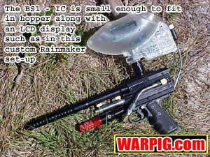 Now
lets get a little more complex and look at a sample circuit for a practical
paintgun. Well also consider more carefully our looping structure,
so that our program can be more modular. I have a Basic Stamp that
I have built into a Revolution Loader with an LCD and a pair of MOSFETS.
By keeping my main program modular, I need to only tweak certain sections
of it to swap the loader bewteen a single solenoid Rainmaker, single solenoid
SuperNova ET, and a dual solenoid automated PMI-1 conversion.
Now
lets get a little more complex and look at a sample circuit for a practical
paintgun. Well also consider more carefully our looping structure,
so that our program can be more modular. I have a Basic Stamp that
I have built into a Revolution Loader with an LCD and a pair of MOSFETS.
By keeping my main program modular, I need to only tweak certain sections
of it to swap the loader bewteen a single solenoid Rainmaker, single solenoid
SuperNova ET, and a dual solenoid automated PMI-1 conversion.