  |
|
|
|
|
|
|
| |
|
|
|
|
|
|
What
do you think?
|
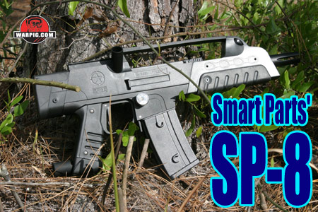
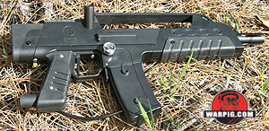
SP-8 By Bill Mills - Photos by Dawn Mills - Apr 2006 How It Works Overview - How It Works - Disassembly - Testing - Raw Test Data
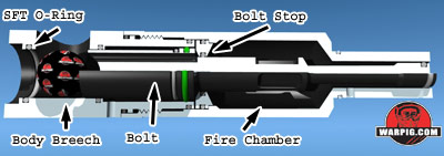
Beneath the outer shell lie the front body breech and the fire chamber the heart of the SP-8. Housed inside of the fire chamber is the SP-8s bolt, which serves both as the bolt and the spool valve to control the flow of exhaust gas used to fire the paintball. These parts, as well as the electronics and solenoid valve are identical to their counterparts on the Ion, even sharing the same part numbers. This means that SP-8 can take advantage of the existing market of internal accessories, such as bolts, QEVs, and electronics upgrades for the Ion. Both the SP-8 and the Ion operate similar to Smart Parts Shocker SFT in that their bolt is also the core of their valve. Their design is simpler, however because only one pilot air source is needed to control the SP-8 bolts position.
Instead of needing a four-way solenoid valve to deliver gas pressure to one side of the bolt to retract it, and another to push it forward and fire, the SP-8s solenoid valve only drives gas to the front of the bolt, pushing it back. When the solenoid valve is activated the airspace in front of the bolt is allowed to vent freely, and air pressure in the fire chamber the same air that fires the ball is used to push the bolt forward, making the SP-8 a blowforward electropneumatic spool valve paintgun.
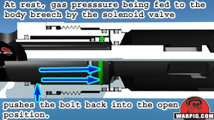
The firing sequence for the SP-8 starts when the paintgun is at rest. At this point, there is a paintball sitting in the breech, and the bolt is in its rear position. Regulated, low pressure gas flows through a hose from the vertical regulator, passes through a Y connection in the solenoid valve and through another hose to the rear of the fire chamber. In some pneumatics terminology, the fire chamber is called an accumulator, as that is where the gas that is going to be used to fire the paintball accumulates, in preparation for the shot. The gas in the fire chamber is prevented from escaping by the bolt. The rear half of the bolt fits into an o-ring seal in the bolt stop, which forms the front wall of the fire chamber. In addition to simply waiting to fire the paintball, the gas in the fire chamber is putting pressure on the back of the bolt, exerting a forward force. The Y connection in the SP-8s solenoid valve also directs gas through a second hose. This hose directs low pressure gas to a narrow airspace in the body breech. This gas presses against a ridge in the bolt, pressing it back toward the rear of the marker. Although the gas in the front and rear of the bolt is at the same pressure. The ridge and seal on the bolt offer more surface area than the diameter of the bolt section which extends into the fire chamber. Because force from gas pressure directly correlates to both pressure and surface area, when the same pressure is applied to both sides of the SP-8s bolt more force is generated in the front than the back, so the bolt is pushed to the rear, open position.
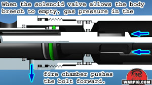
When the SP-8s trigger is pulled, the electronics in the circuit board check to make sure there is a ball in the breech (if Vision mode is turned on) and when ready, send power to the guns solenoid valve. When the solenoid valve actuates it has no effect on the gas being routed to the fire chamber, it simply blocks the gas that was being sent to the body breech and allows the airspace in the body breech to be vented to the atmosphere.
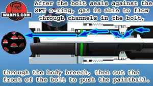
With no more resistance in the front of the bolt, the gas pressure in the fire chamber pushes the bolt forward. This pushes the paintball past the ball detents into the rear of the barrel, and seals the bolt against the SFT o-ring in the breech. At the forward end of its stroke, a series of grooves in the rear of the bolt pass under the central o-ring of the bolt stop. The gas from the fire chamber is then able to flow through these grooves, into the airspace of the body breech, and through a series of holes in the front of the bolt to the barrel, where it pushes the paintball up to the desired velocity. After the dwell time has expired, the SP-8s circuit board stops sending power to the solenoid valve. The valve resets, and once again sends low-pressure gas to the body breech. This gas forces the bolt back to the rear position sealing against the bolt stop, while the gas line to the fire chamber remains open, recharging it to the necessary pressure to fire the next shot. Setup of the SP-8 for review was simple. A set of hex wrenches, open end wrench and barrel blocking bag were included. Aside from the installation of a battery (also included) it was basically ready to go out of the box, the barrel was already installed. A Phillips head screwdriver was needed to remove the two grip panel screws and open one side of the wraparound grip, where a 9volt battery was attached to the battery clip before being sealed back up inside. For review, a 4500 psi high pressure output (about 800 psi) Crossfire screw in compressed air system was used. It was important when gassing up the SP-8 to screw the air system in slowly, to gently raise the pressure in the gun, rather than hitting it with a sudden burst. While the SP-8 can run on both compressed air and CO2, it is very important to note that liquid CO2 is not healthy for it. If CO2 is used in a tank on the bottom-line, it should be done with an anti-siphon tank. The use of a vertical CO2 tank in a pack with a remote line also will prevent liquid CO2 from feeding. The SP-8 uses a right side angled feedneck, in order to provide a clear line of sight for scopes, night vision gear, or other sights mounted on the top sight rail. Angled feeds were the dominant style for paintguns in the 1990s, but lost market share to designs with vertical feed necks in the new millennium as tournament paintball play focused on high rates of fire and walking a paint stream to target where a single aimed shot was less important.
Changing firing modes, or adjusting timing required opening the SP-8s grip. A single programming button, and pair of feedback LEDs (Light Emitting Diodes) one in red, and one in yellow, allow for adjustment. Because all settings that can effect timing and rate of fire are located within the grip and inaccessible without tools, the SP-8 can be locked into field-legal semi-auto where required.
Pressing the power button will make the change to the settings indicated by the LEDs. The SP-8 does not make any indication of how it is set-up. In order to select a specific setting one needs to set a value down to zero or up to the maximum, then counted adjustments up or down until they reach to the desired setting. When the programming button is first
pressed, the yellow LED will light solidly, pressing the power button at
this point will increase the dwell time, or the amount of time that the
circuit applies power to the solenoid valve to fire a paintball.
Pressing the programming button again will cause the Ion circuit board
to hold the red LED on solidly. Then each press on the power button
will decrease the dwell time. When a setting reaches either the bottom
or top of the range over which it can be adjusted, the red LED will flash
momentarily.
Similarly, the rate of fire setting, which is the amount of time the Ion waits after firing before the next shot can be fired, is set with a blinking red LED indicating that the ROF can be increased, or the blinking yellow indicating that it can be decreased.
The final setting which can be adjusted
is the firing mode. The double-blinking of the yellow LED indicates
that the firing mode value can be increased, while double blinking of the
red LED indicates that it is being decreased. The first mode (0)
is basic semi-automatic. The second (1) is rebound, similar to the
rebound modes in the Shocker SFT and Nerve, it adds shots in addition to
those generated by trigger pulls after the first few pulls of a string.
The third mode (mode 2) is a three shot burst. Pulling and holding
the trigger results in three shots being fired. The fourth and final
mode (3) is full automatic. Pressing and holding the trigger causes
the SP-8 to fire repeatedly until the trigger is released. While
the SP-8 can fire at up to 17 balls per second in semi-auto and rebound
modes, the burst and full automatic modes are capped at 10 balls per second.
Continue to Disassembly
|
| Copyright © 1992-2019
Corinthian Media Services. WARPIG's webmasters can be reached through our feedback form. All articles and images are copyrighted and may not be redistributed without the written permission of their original creators and Corinthian Media Services. The WARPIG paintball page is a collection of information and pointers to sources from around the internet and other locations. As such, Corinthian Media Services makes no claims to the trustworthiness or reliability of said information. The information contained in, and referenced by WARPIG, should not be used as a substitute for safety information from trained professionals in the paintball industry. |

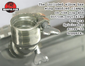 Because
of the right side feed arrangement, an elbow is needed to mount a hopper
on the SP-8. Smart Parts included a Spin Loader elbow packaged with
the SP-8 used for review. This elbow features thumb-screws to clamp
both to the paintgun and the hopper. The elbow fit properly with
a Ricochet Apache loader with its neck o-rings removed, and both HALO and
eVLution with sanded feednecks were a proper fit (unsanded were too large.)
The Spin Loader elbow is produced by Avalon Manufacturing, and is also
threaded to accept their E-Tron non-agitated loaders, which screw into
the elbow rather than press fitting. During review, HALO, Apache
and VLocity loaders were used.
Because
of the right side feed arrangement, an elbow is needed to mount a hopper
on the SP-8. Smart Parts included a Spin Loader elbow packaged with
the SP-8 used for review. This elbow features thumb-screws to clamp
both to the paintgun and the hopper. The elbow fit properly with
a Ricochet Apache loader with its neck o-rings removed, and both HALO and
eVLution with sanded feednecks were a proper fit (unsanded were too large.)
The Spin Loader elbow is produced by Avalon Manufacturing, and is also
threaded to accept their E-Tron non-agitated loaders, which screw into
the elbow rather than press fitting. During review, HALO, Apache
and VLocity loaders were used.
 Gassed
up and loaded with paint, it was time to try out the SP-8. Pressing
and holding the power button for about 2 seconds turned it on, with the
button blinking red to indicated that the Vision system was active.
A short press of the button would turn off Vision mode, allowing the SP-8
to be dry-fired without paint. Non-Vision operation was indicated
by a double-blink pattern on the LED behind the power button. During
setup, the faux ammo magazine was removed and velocity adjustment was performed
with an adjustable wrench turning the wrench flats on the bottom of the
guns vertical regulator. With DraXxus Hellfire paint, the velocity
out of the box was 275 fps, and quickly adjusted to an average 285.
The pressure gauge integrated into the magazine holder was used to ensure
that the pressure was not adjusted to the recommended limit of 200 psi.
Gassed
up and loaded with paint, it was time to try out the SP-8. Pressing
and holding the power button for about 2 seconds turned it on, with the
button blinking red to indicated that the Vision system was active.
A short press of the button would turn off Vision mode, allowing the SP-8
to be dry-fired without paint. Non-Vision operation was indicated
by a double-blink pattern on the LED behind the power button. During
setup, the faux ammo magazine was removed and velocity adjustment was performed
with an adjustable wrench turning the wrench flats on the bottom of the
guns vertical regulator. With DraXxus Hellfire paint, the velocity
out of the box was 275 fps, and quickly adjusted to an average 285.
The pressure gauge integrated into the magazine holder was used to ensure
that the pressure was not adjusted to the recommended limit of 200 psi.
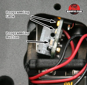 In
all, there are three settings which can be adjusted on the SP-8s circuit
board. Programming begins by turning on the SP-8 with the grip opened,
and pressing the programming button. Each time the programming button
is pressed, the setting being adjusted will be changed, and the pattern
of blinking LEDs will indicate the selected setting. Each setting
may be adjusted either up or down, depending on the pattern with which
the LEDs blink.
In
all, there are three settings which can be adjusted on the SP-8s circuit
board. Programming begins by turning on the SP-8 with the grip opened,
and pressing the programming button. Each time the programming button
is pressed, the setting being adjusted will be changed, and the pattern
of blinking LEDs will indicate the selected setting. Each setting
may be adjusted either up or down, depending on the pattern with which
the LEDs blink.
 For
players who rely on the Vision anti-chop eye of the SP-8 and want the maximum
possible rate of fire available to them, the ROF should be set to minimum
value. That does not mean that it is without purpose. A player
choosing not to use the Vision mode, might increase the ROF delay in order
to limit how fast the SP-8 shoots, to avoid chopping paint when using a
slower agitating hopper. A more practical use is in restricting rate
of fire for scenario games that allow full auto with a rate of fire limit,
or tournaments that restrict total rate of fire such as the PSP and CFOA
15 ball per second limits.
For
players who rely on the Vision anti-chop eye of the SP-8 and want the maximum
possible rate of fire available to them, the ROF should be set to minimum
value. That does not mean that it is without purpose. A player
choosing not to use the Vision mode, might increase the ROF delay in order
to limit how fast the SP-8 shoots, to avoid chopping paint when using a
slower agitating hopper. A more practical use is in restricting rate
of fire for scenario games that allow full auto with a rate of fire limit,
or tournaments that restrict total rate of fire such as the PSP and CFOA
15 ball per second limits.