  |
|
|
|
|
|
|
| |
|
|
|
|
|
|
What
do you think?
|

BT-16 Elite By Bill Mills - Sept Photos By Dawn Mills - 2005 Overview - How it Works - Disassembly - Testing - Raw Test Data Disassembly Dissassembly of the BT-16 for maintenance and repair is rather straightforward. Included with the Elite are a set of three hex wrenches, and spare o-rings. Before any components are disassembled, the BT-16 should be unloaded, and degassed. The foregrip is removed simply by unlocking its bottom knob, and sliding it forward, off of the Picatinny rail. The rail can then be removed by taking out the screw at its front and back. The rail lifts off to reveal a brass cylinder which slides out, and contains the spring and steel ball bearing of the ball detent. A small hex screw, which is locked in place with thread locking compound, secures the barrel adapter in place. These parts are reassembled simply by reversing the disassembly procedure.
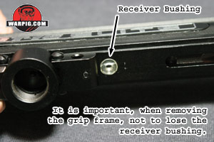
A clear urathane spacer sits in an indentation in the bottom of the receiver. It is important to keep an eye on this part when removing the grip frame, so that it does not get dropped and lost.
A steel cocking rod sticks out of the top of the hammer, and is pulled back by the t-bar for cocking. This lifts straight out the top of the receiver.
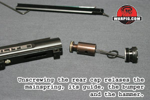
At this point the rear cap simply unscrews from the back of the receiver. A pin in the top of the grip frame keeps the cap from vibrating loose when the BT-16 is assembled. Along with the cap, the spring, its guide, and the large o-ring which acts as a bumper for the hammer, all come out the back of the receiver.
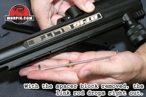
A small clear piece of plastic, the spacer block sits in the center of the top of the receiver, once it is removed, the steel link rod connecting the bolt and hammer can be dumped out the top. While a variety of tools could be used to remove the block, it is easily done with an o-ring pick.
The hammer will then slide freely out the rear of the receiver.
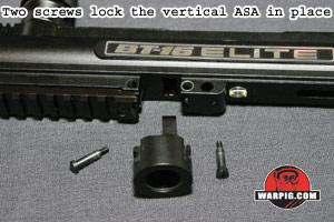
Removing the valve requires first removing the ASA. Two screws on either side of the ASA need to be removed with a straight slot screwdriver, and the adapter then slides easily out. As long as the velocity screw is screwed in far enough that it wont catch on the receiver, the valve assembly can then be slid out the rear of the receiver.
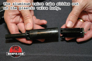
The valve tube slides out the back of the valve body. While it is in the gun, the ASA fits up through the valve body and into a slot in the front of the valve tube, thus preventing the tube from sliding loose in the body. Rarely will a BT-16 need to be disassembled past this point.
In the opposite of disassembly, the valve tube slides into the valve body, the bolt onto the front, and they go back into the receiver. An easy way to know when the valve body is in position is that the velocity adjustment screw will be aligned with the adjuster opening in the receiver. The hammer slides into the back and is connected to the bolt with the link rod, which is held in place with the spacer block.
The mainspring and its guide (which fits in the rear end of the spring) slide in between the hammer and rear plug, with the rear bumper o-ring going in around the spring. Keeping an eye that the urathane spacer
is in its position of the bottom of the receiver, the gas line can be screwed
back into the ASA, and the grip frame re-secured to the receiver with its
pins.
>Continue to Testing |
| Copyright © 1992-2019
Corinthian Media Services. WARPIG's webmasters can be reached through our feedback form. All articles and images are copyrighted and may not be redistributed without the written permission of their original creators and Corinthian Media Services. The WARPIG paintball page is a collection of information and pointers to sources from around the internet and other locations. As such, Corinthian Media Services makes no claims to the trustworthiness or reliability of said information. The information contained in, and referenced by WARPIG, should not be used as a substitute for safety information from trained professionals in the paintball industry. |

 A
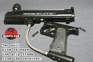
pair of push pins hold the grip frame onto the receiver. These tend
to fit rather stiffly, so removing them may require pressing on their rounded
ends with a hex wrench and pushing them through to the far side of the
frame. The grip frame will then hang by the braided steel gas line,
which can be disconnected from the vertical ASA simply by unscrewing.
A
pair of push pins hold the grip frame onto the receiver. These tend
to fit rather stiffly, so removing them may require pressing on their rounded
ends with a hex wrench and pushing them through to the far side of the
frame. The grip frame will then hang by the braided steel gas line,
which can be disconnected from the vertical ASA simply by unscrewing.
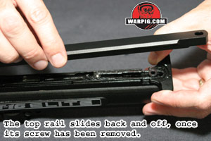 A
hex screw in the top of the sight rail is removed to unlock it. Once
unlocked the rail can be slid back, along with the cocking handle, to a
point where it lifts off. The cocking handle, its spring and the
springs retainer then lift up out of the receiver, along with the sight
rails standoff spacer.
A
hex screw in the top of the sight rail is removed to unlock it. Once
unlocked the rail can be slid back, along with the cocking handle, to a
point where it lifts off. The cocking handle, its spring and the
springs retainer then lift up out of the receiver, along with the sight
rails standoff spacer.
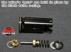 At
the front of the valve tube, the valve o-ring rests inside a groove.
When the valve is under pressure, this o-ring seals up against the face
of the top of the ASA. It can be removed with an o-ring pick.
Below it lie the valve washer, the spring, and the valve core. A
leak of gas down the barrel will likely be due to damage, or debris on
the cup seal, which is located on the valve core. The cup seal seals
up against a brass seal face which sits on top of a urathane o-ring inside
the rear of the valve tube.
At
the front of the valve tube, the valve o-ring rests inside a groove.
When the valve is under pressure, this o-ring seals up against the face
of the top of the ASA. It can be removed with an o-ring pick.
Below it lie the valve washer, the spring, and the valve core. A
leak of gas down the barrel will likely be due to damage, or debris on
the cup seal, which is located on the valve core. The cup seal seals
up against a brass seal face which sits on top of a urathane o-ring inside
the rear of the valve tube.
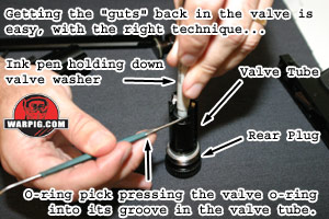 Reassembling
the valve can be a bit tricky. All of the components easily fit inside,
but the pressure of the valve spring can make it difficult to get the valve
o-ring seated inside of its groove. An effective way to quickly get
the valve tube components reassembled is to start by placing the rear valve
o-ring and the brass valve spacer (the seal face) in place, followed by
the core and spring. The washer then sits on the spring, with the
o-ring on top. Setting valve tube on top of the back plug will allow
it to sit upright without putting any pressure on the valve pen.
An ink pen can then be used to push down on the center of the valve washer,
compressing the spring, while an o-ring pick reaches around it to pop the
o-ring into its groove.
Reassembling
the valve can be a bit tricky. All of the components easily fit inside,
but the pressure of the valve spring can make it difficult to get the valve
o-ring seated inside of its groove. An effective way to quickly get
the valve tube components reassembled is to start by placing the rear valve
o-ring and the brass valve spacer (the seal face) in place, followed by
the core and spring. The washer then sits on the spring, with the
o-ring on top. Setting valve tube on top of the back plug will allow
it to sit upright without putting any pressure on the valve pen.
An ink pen can then be used to push down on the center of the valve washer,
compressing the spring, while an o-ring pick reaches around it to pop the
o-ring into its groove.