  |
|
|
|
|
|
|
| |
|
|
|
|
|
|
NOTE:
The Revolution electronics have been improved since this test. Click
here to see how the X-Board tests in comparison.
What
do you think?
|
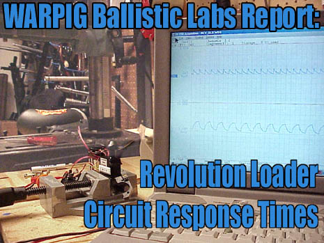
WARPIG Ballistic Labs Report: Revolution Response Times by Bill Mills The Background The ViewLoader Revolution loader was released at the NPPL World Cup tournament in 1997, and quickly became the standard loader used on high performance paintguns. Powered by a pair of 9 volt batteries, it features an infra-red ball sensor in its neck and electronics to drive a motorized agitator in the loader body. As paintballs feed from the loader into the paintgun, the motor sits silent. However, if the balls are jammed in the hopper, the infrared sensor in the neck detects the empty space, and the control circuitry activates the agitator, which breaks up the jam so additional paintballs can feed into the paintgun. Jem series ViewLoaders with transparent and semitransparent bodies have been popular for their style, but with the Revolution loader, they caused problems. Infrared sunlight could enter through the semitransparent loader neck and activate the agitator when it was not needed. This created undue noise and battery drain. After Brass Eagle purchased ViewLoader, a temporary solution was to mold Jem loader bodies with solid black necks.
The Question Many players have praised this new board for this feature, while others have complained that it is less responsive than the original Revolution circuit board, resulting in less reliable feeding. Rather than rely on a subjective viewpoint, we put the Revolution circuit boards through WARPIG Ballistic Labs for testing with a scientific approach. The Test For this test we compared the circuit board from an original 1997 Revolution to one with a manufacturing date of March 24, 2000. The 1997 Revolution was out of the first production batch - serial number #0089. To test circuit response times, the complete internal assemblies (control circuit, agitator motor, infrared sensor emitter pair) were removed from the loader bodies. They were powered by a pair of 9 volt batteries wired in series, linked to the boards with external battery clips.
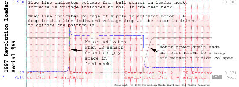
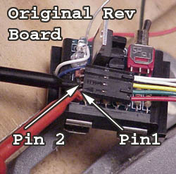
Pin 1 of the connector is the power source for the agitating motor. This pin shows voltage when the motor is not running, but when the motor is running, it creates a voltage drop on Pin 1 that is easily detected on the graphs from the wave form recorder. The testing consisted of simulating the presence of a ball in the feed neck by the presence of a human finger. Removing the finger from the infrared beam simulated a ball dropping out of the feed neck. The Results With the voltage traces from Pin1 and Pin2 overlaid on a time based graph, any delay between the time the circuit board senses a clear feed neck and the time the agitator begins spinning becomes clearly evident. On the graphs, the voltage of Pin 1 (motor power) is represented as a grey line. Pin 2 (sensor) is represented as a blue line. Time progresses from left to right, and the dotted red grid lines are .167 seconds apart. With the IR beam blocked, the blue line is low, indicating that no power is coming back from the IR sensor. The grey line is high indicating that the motor is not drawing power. When the IR beam is no longer blocked, the blue line shifts upward, indicating an increase in voltage back from the sensor. When the motor spins, the grey line drops, indicating a voltage drop in the power supplied to the motor. Click on the graphs below to see a representative sections of the test results in full detail.
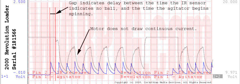
Through a series of ten test activations with each loader, the sample traces indicated a virtually indistinguishable time gap between the signal and the activation of the agitator on the original Revolution. The newer board was a different story. With the new Revolution board neither the voltage from the IR sensor, or the voltage drop caused by the motor were constant or as great. Both were a regularly repeating spiked wave pattern, the power drop from the motor cycled at two times the frequency of the signal coming through the IR sensor. A gap was clearly evident between the IR sensor's signal and the activation of the motor. Correlating the two signals, it appears that the length of the delay depends on the amplitude of the wave from the IR sensor at the time the beam is allowed to reach the sensor. In 10 trials, the delay times ranged from 0.133 seconds to 0.267 seconds. The average response time from the 10 samples was 0.162 seconds. The Conclusion Of the two loaders tested, the newer model definitely had slower response times. While this delay does not directly correlate to the rate at which paint will feed from the loader, it does directly affect the time it will take to unjam stuck paintballs in the main loder body.
|
| Copyright © 1992-2019
Corinthian Media Services. WARPIG's webmasters can be reached through our feedback form. All articles and images are copyrighted and may not be redistributed without the written permission of their original creators and Corinthian Media Services. The WARPIG paintball page is a collection of information and pointers to sources from around the internet and other locations. As such, Corinthian Media Services makes no claims to the trustworthiness or reliability of said information. The information contained in, and referenced by WARPIG, should not be used as a substitute for safety information from trained professionals in the paintball industry. |
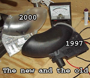 In
the year 2000, Brass Eagle shipped Revolutions with a newer, improved circuit
board. The new board featured electronics that would not be fooled
by sunlight.
In
the year 2000, Brass Eagle shipped Revolutions with a newer, improved circuit
board. The new board featured electronics that would not be fooled
by sunlight.
 One
at a time, the boards were connected to a dual trace wave form recorder.
The ground line of the wave form recorder was connected to the negative
battery terminal on the loader circuit. Channel one of the recorder
was connected to pin 2 of the circuit board connector. Pin 2 is wired
to the infrared detector, and shows an increase in voltage when infrared
light from the infrared LED on one side of the neck shines across an empty
gap. When a ball, finger, or other opaque object blocks the light
beam, the voltage on pin 2 drops.
One
at a time, the boards were connected to a dual trace wave form recorder.
The ground line of the wave form recorder was connected to the negative
battery terminal on the loader circuit. Channel one of the recorder
was connected to pin 2 of the circuit board connector. Pin 2 is wired
to the infrared detector, and shows an increase in voltage when infrared
light from the infrared LED on one side of the neck shines across an empty
gap. When a ball, finger, or other opaque object blocks the light
beam, the voltage on pin 2 drops.