Electronic Basics
by Bill Mills
Continued....
On a schematic,
a resistor is a squiggly line. It is not current specific (power
can run through it in either direction). There are also variable
reistors. These are resistors that can be adjusted to provide more
or less resistance, just like a water faucet that can limit the flow of
water out of a  pipe.
A common application of variable resistors is the volume knob on an older
stereo, or a dimmer switch for a light bulb. A variable resistor
is represented in a schematic as a resistor symbol with an arrow at an
angle through the center. pipe.
A common application of variable resistors is the volume knob on an older
stereo, or a dimmer switch for a light bulb. A variable resistor
is represented in a schematic as a resistor symbol with an arrow at an
angle through the center.
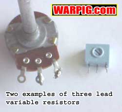
Some variable
resistors have three terminals. The center lead is common, and turning
or sliding (depending on the type) the control knob in one direction will
increase the resistance to one lead while decreasing it to the other.
These three terminal variabile resistors are represented as a resistor
with the common terminal as an arrow pointing to the center.
 Just
like power sources, resistors can be wired in series (end to end) or in
parallel (side by side). When wired in parallel more current flows
across the leg with the less resistance. Current flow must be calculated
for each of the parallel resistors and then added together. When
the resistors are wired in series, the resistance is simply added together. Just
like power sources, resistors can be wired in series (end to end) or in
parallel (side by side). When wired in parallel more current flows
across the leg with the less resistance. Current flow must be calculated
for each of the parallel resistors and then added together. When
the resistors are wired in series, the resistance is simply added together.
Rtotal = R1 + R2 + R3
.
So, if a circuit
calls for 10,500 Ohms of resistance, that can be achieved by putting a
500 Ohm resistor in series with a 10K resistor.
 Things
get more complicated when we start mixing and matching series and parallel
patterns together, and take up the better part of a few lectures in an
introductory electronics course. The good news is that for microprocessor
based control circuits on a paintgun, we dont need to know much more than
this to b e very productive. Things
get more complicated when we start mixing and matching series and parallel
patterns together, and take up the better part of a few lectures in an
introductory electronics course. The good news is that for microprocessor
based control circuits on a paintgun, we dont need to know much more than
this to b e very productive.
A
capacity for charges
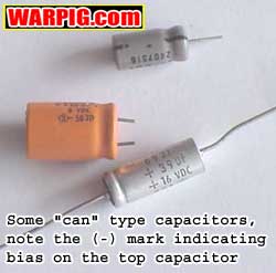 Another
key electronic component is the capacitor. In the simplest terms
a capacitor is nothing more than a pair of plates with a non-conductor
between them. The plates can be charged, and later discharged.
Building electrical potential in a capacitor is referred to as biasing
it. Capacitors play a very important role electronic frequency generating
and filtering circuitry and come in a wide variety of shapes and sizes,
depending on their particular materials. Fortunately basic input
and output circuits to a microprocessor wont rely on capacitance, so we
can pretty much skip right on past capacitors. The main place they
would come into play is filtering switch bounce out of trigger signals
(which can also be done in Another
key electronic component is the capacitor. In the simplest terms
a capacitor is nothing more than a pair of plates with a non-conductor
between them. The plates can be charged, and later discharged.
Building electrical potential in a capacitor is referred to as biasing
it. Capacitors play a very important role electronic frequency generating
and filtering circuitry and come in a wide variety of shapes and sizes,
depending on their particular materials. Fortunately basic input
and output circuits to a microprocessor wont rely on capacitance, so we
can pretty much skip right on past capacitors. The main place they
would come into play is filtering switch bounce out of trigger signals
(which can also be done in  software)
and dampening radio interference generated by motors. Capacitance
is measured in Farads, and the most practical unit is the MicroFarad, or
uF, often simply written as u. Depending on the type, capacitors
may not be current specific, or may have one side meant for positive bias
this will be indicated in any schematic which requires a capacitor, and
the case will in some way indicate the positive or negative lead. software)
and dampening radio interference generated by motors. Capacitance
is measured in Farads, and the most practical unit is the MicroFarad, or
uF, often simply written as u. Depending on the type, capacitors
may not be current specific, or may have one side meant for positive bias
this will be indicated in any schematic which requires a capacitor, and
the case will in some way indicate the positive or negative lead.
A
magnetic personality
Magnets are especially
important to us, as electromagnetism is one of the most practical ways
to convert electrical energy into mechanical movement. When electrical
current flows through a coil of wire, it generates a magnetic field.
This field can push or pull against a magnet causing it to move.
Alternating fields
in coils of wire are what make electric motors spin. Solenoids are
simpler electromagnetic devices. They are just a coil of wire, and
when current passes through them, they pull a magnet toward their center.
A common place they are found is in the electronic door locks of cars
and in paintball guns. Some paintguns, like the Airgun 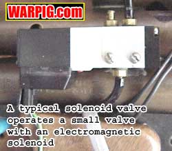 Designs
E-Mag use a large heavy duty solenoid to operate the mechanical portion
of the paintgun (the sear on the E-Mag would moved by the trigger on a
standard Automag). While this is a great approach for products like
the Centerflag Hyperframe, where the solenoid is added to an existing mechanical
system, the solenoid is having to do a lot of work. The more pull
the solenoid needs to operate, the more electrical resistance it creates,
and the more wattage is needed to get the job done. Many other paintguns
take a different approach. The Angel, Shocker, Matrix, Bushmaster
and others use small solenoid valves. In these pre-fabricated valves,
a small solenoid is used to operate a small spool valve (very much like
the 4 way valve in an Autococker) to re-direct control gasses that drive
a pneumatic cylinder. In this way the electrical circuit is only
doing a small amount of mechanical work, and letting the paintguns gas
supply do the real work. The circuitry and power supply needed to
drive a small solenoid valve does not need to be as rubust as that for
a larger mechanical drive solenoid. Designs
E-Mag use a large heavy duty solenoid to operate the mechanical portion
of the paintgun (the sear on the E-Mag would moved by the trigger on a
standard Automag). While this is a great approach for products like
the Centerflag Hyperframe, where the solenoid is added to an existing mechanical
system, the solenoid is having to do a lot of work. The more pull
the solenoid needs to operate, the more electrical resistance it creates,
and the more wattage is needed to get the job done. Many other paintguns
take a different approach. The Angel, Shocker, Matrix, Bushmaster
and others use small solenoid valves. In these pre-fabricated valves,
a small solenoid is used to operate a small spool valve (very much like
the 4 way valve in an Autococker) to re-direct control gasses that drive
a pneumatic cylinder. In this way the electrical circuit is only
doing a small amount of mechanical work, and letting the paintguns gas
supply do the real work. The circuitry and power supply needed to
drive a small solenoid valve does not need to be as rubust as that for
a larger mechanical drive solenoid.
 The
schematic symbol for a solenoid is a coil with a core in the center. The
schematic symbol for a solenoid is a coil with a core in the center.
An important
thing to know about solenoids is that when the current driving them is
released the magnetic field it created will collapse and the collapsing
field will generate an electrical current in the opposite direction.
Especially with sensitive microprocessors in a circuit, it is important
to design circuits that prevent this backwash of current from destroying
part of the circuitry. And, for the record, the word is solenoid
- S O L E N O I D, not "selenoid." I don't know why, but I get a
couple of e-mails a week from people asking about "selenoid" valves.
Turn
me on!
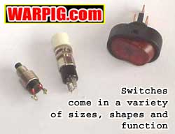 Switches
are quite important. Switches and pushbuttons come in an unbelievable
array of sizes, shapes and styles. The important things to know about
them are the style, and contacts. Basically a switch either makes
or breaks an electrical connection by touching conductors together.
When the contacts are touching, current can flow from one side of the switch
to the other and the switch is said to be closed. When the contacts
are open and no current can flow, the switch is open. Momentary switches
return to their off-state when they are released. The typical button
that controls a car horn is a normally open momentary switch. When
it is pressed it closes a circuit delivering power to the car horn, and
when it is released the circuit breaks again. This is the type of
push button that is needed Switches
are quite important. Switches and pushbuttons come in an unbelievable
array of sizes, shapes and styles. The important things to know about
them are the style, and contacts. Basically a switch either makes
or breaks an electrical connection by touching conductors together.
When the contacts are touching, current can flow from one side of the switch
to the other and the switch is said to be closed. When the contacts
are open and no current can flow, the switch is open. Momentary switches
return to their off-state when they are released. The typical button
that controls a car horn is a normally open momentary switch. When
it is pressed it closes a circuit delivering power to the car horn, and
when it is released the circuit breaks again. This is the type of
push button that is needed  to
receive an electronic signal from a trigger, or for use as a mode-select
button. A single pole, single throw switch is what is used for a
light switch in a home. It rests in either an open or closed position,
delivering current or not, depending on whether it is on, or off.
SPST switches are used for power switches in paintguns and other small
electronics. Switches are represented in schematics by diagrams that
show the layouts of their contacts. to
receive an electronic signal from a trigger, or for use as a mode-select
button. A single pole, single throw switch is what is used for a
light switch in a home. It rests in either an open or closed position,
delivering current or not, depending on whether it is on, or off.
SPST switches are used for power switches in paintguns and other small
electronics. Switches are represented in schematics by diagrams that
show the layouts of their contacts.
One
way only!
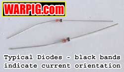 Diodes
are electronic one way gates. They let current pass through them
in one direction only. In the schematic diagram, there are two circuits
with light bulbs. In the circuit on the left, the diode is aligned
in the circuit properly, and current flows through it to light the bulb.
In the other circuit, the diode is in opposition to the circuit, and it
blocks the current, preventing the bulb from lighting. Diodes
are electronic one way gates. They let current pass through them
in one direction only. In the schematic diagram, there are two circuits
with light bulbs. In the circuit on the left, the diode is aligned
in the circuit properly, and current flows through it to light the bulb.
In the other circuit, the diode is in opposition to the circuit, and it
blocks the current, preventing the bulb from lighting.
Putting a diode
in series with a solenoid is one way to protect circuitry from the backwash
of current when the solenoids field collapses. The schematic symbol
for a diode is a triangle pointing toward the negative side of the circuit,
with a small cross-bar.
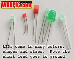 LEDs
are a specific variety of diodes which emit light. Because of their
very low current drain relative to their brightness, they are superior
to light bulbs in display and compact electronic applications. Since
LEDs are diodes you must remember that current can only pass through them
in one direction. The schematic symbol for an LED is the same as
for a normal diode, but has small wavy lines coming out of it to indicate
light. LEDs
are a specific variety of diodes which emit light. Because of their
very low current drain relative to their brightness, they are superior
to light bulbs in display and compact electronic applications. Since
LEDs are diodes you must remember that current can only pass through them
in one direction. The schematic symbol for an LED is the same as
for a normal diode, but has small wavy lines coming out of it to indicate
light.
Transistors
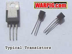 Transistors
come in such a wide variety of materials, shapes and functions that there
are literally whole books about them. Transistors are three lead
devices which function somewhat like a valve. In a most general description,
they control a large amount of current through two of the leads with the
presence or absence of current to the third lead. Often they are
used to amplify signals. A weak signal can be used to control a transistor
that has a large amount of current flowing through it, and the large current
will be an amplified version of the weak signal. From a control aspect,
they can used to turn on or off the flow of current to high drain devices.
This is what really matters to us when designing circuits for paintguns.
A low amperage control current out of a microprocessor can control a transistor
which will then drive a solenoid or solenoid valve. Transistors
come in such a wide variety of materials, shapes and functions that there
are literally whole books about them. Transistors are three lead
devices which function somewhat like a valve. In a most general description,
they control a large amount of current through two of the leads with the
presence or absence of current to the third lead. Often they are
used to amplify signals. A weak signal can be used to control a transistor
that has a large amount of current flowing through it, and the large current
will be an amplified version of the weak signal. From a control aspect,
they can used to turn on or off the flow of current to high drain devices.
This is what really matters to us when designing circuits for paintguns.
A low amperage control current out of a microprocessor can control a transistor
which will then drive a solenoid or solenoid valve.
 Other
special semi-conductors handle tasks like voltage regulation. Just
like a gas regulator controls pressure on a paintgun, a voltage regulator
can limit the voltage supplied by a battery or battery array. Other
special semi-conductors handle tasks like voltage regulation. Just
like a gas regulator controls pressure on a paintgun, a voltage regulator
can limit the voltage supplied by a battery or battery array.
In no way should
this article be seen as anything close to a complete course in electronics.
It will hopefully, at least give you a starting knowledge that is enough
to work with the simple circuit designs needed to integrate a microprocessor
into a circuit for paintgun control. To really get involved and design
your own circuits, self paced instructional books like Basic
Electronics Theory by Delton T. Horn are available from bookstores,
or local libraries.
|